
Compressed gas pump for replica weapon

a gas pump and replica technology, applied in the direction of positive displacement pump components, positive displacement liquid engines, white arms/cold weapons, etc., can solve the problems of reducing the reducing the resistance of the pump, and increasing the losses due to the flat parts of the pump, so as to achieve the effect of reducing the resistance considerably

Inactive Publication Date: 2005-08-25
CYBERGUN
View PDF3 Cites 16 Cited by
  • Summary
  • Abstract
  • Description
  • Claims
  • Application Information

AI Technical Summary

Benefits of technology

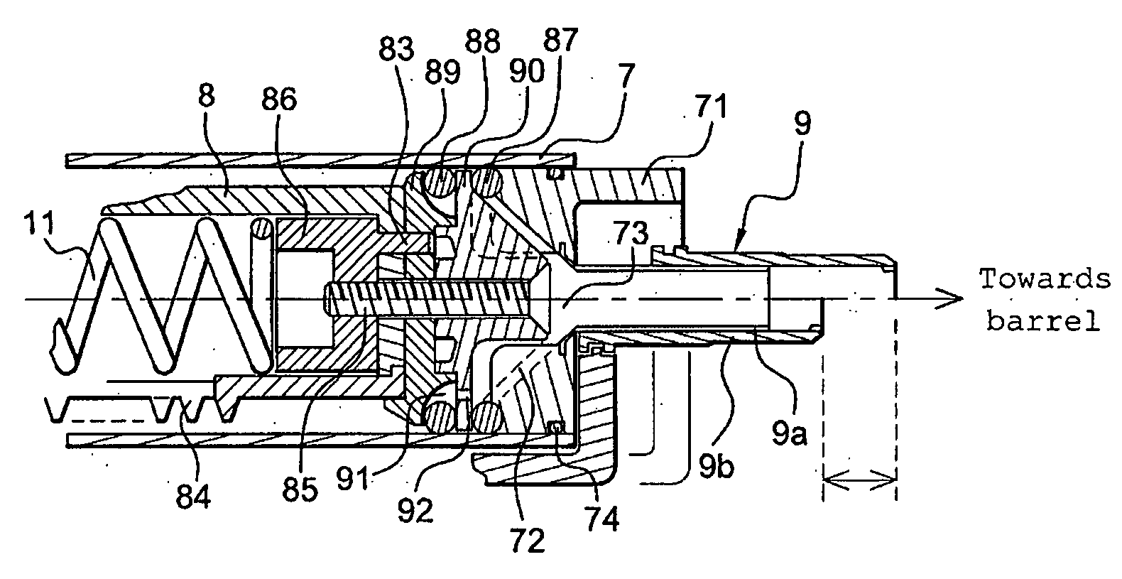
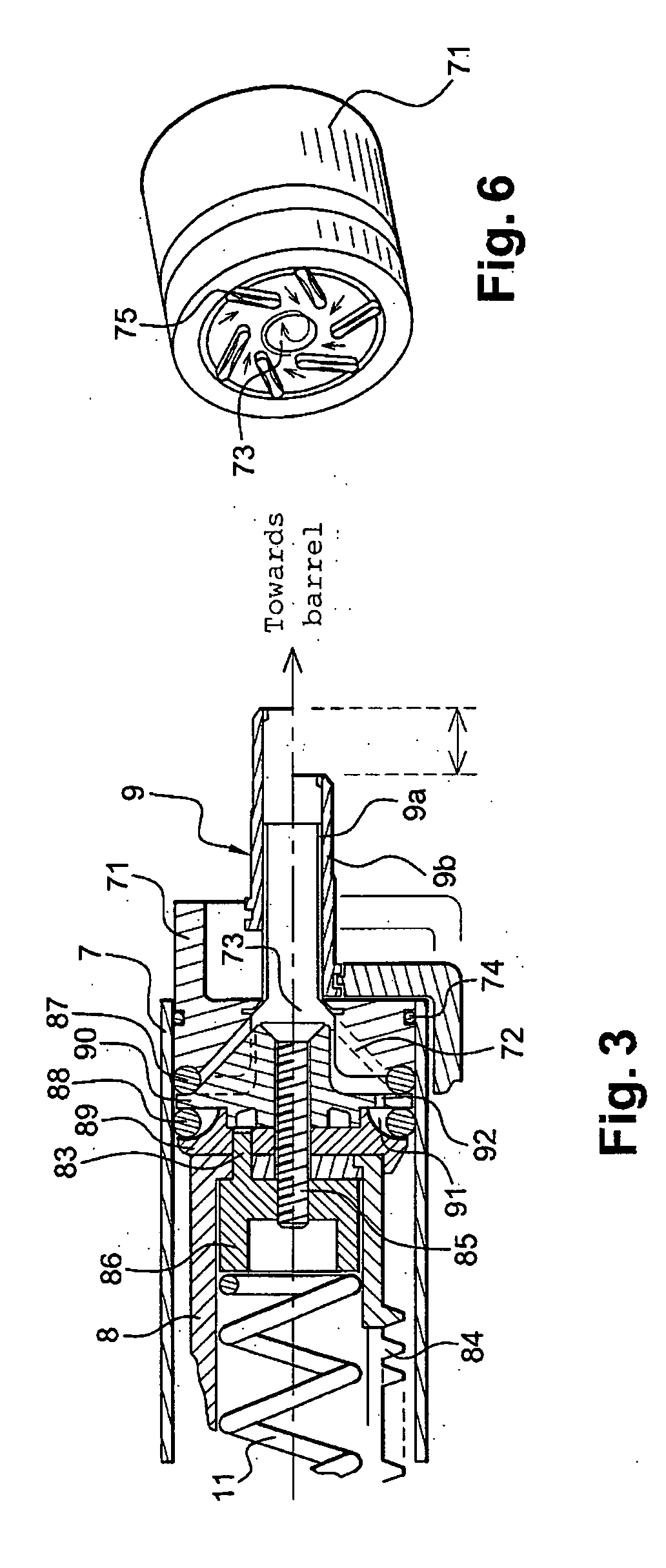
[0022] The invention is specifically intended to rectify the disadvantages of the prior art. To this end, the invention proposes a compressed air or gas pump in which the piston head has a conical shape which engages in the cylinder head, the shape of which is matched to that of the piston head. The cylinder head forms a funnel, which allows the compressed gas to be directed towards the central orifice of the cylinder head, and therefore towards the ejection nozzle. The funnel shape of the cylinder head, associated with the conical shape of the piston head, allows for the resistance to be reduced considerably which is encountered by the gas seeking to escape from the gas retention compartment through the ejection nozzle.

Problems solved by technology

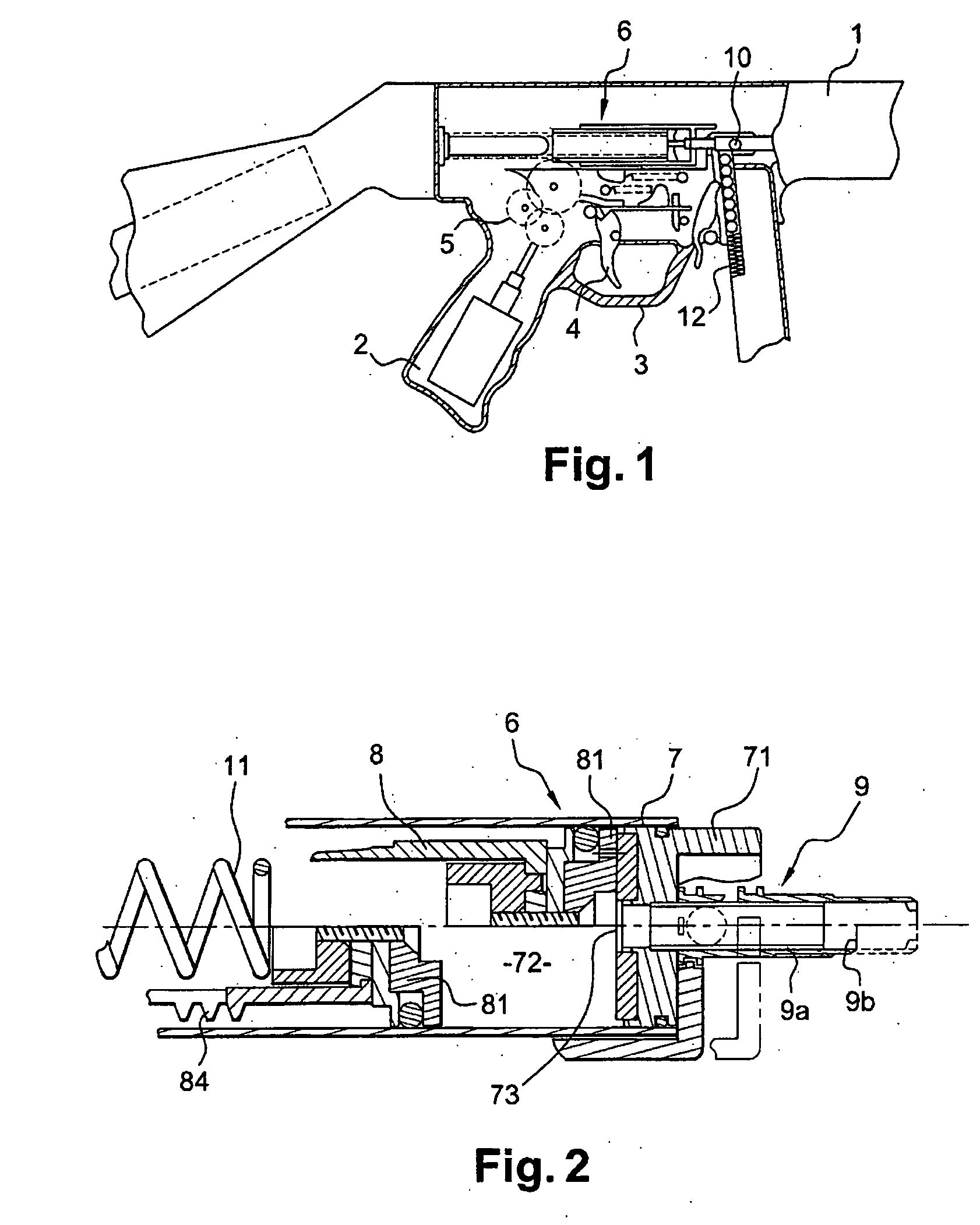
The gas flow seeks to escape through the ejection nozzle 9, but it has difficulty because it creates substantial contradictory turbulence movements.
As a consequence, the piston is slowed down as it approaches the cylinder head, which incurs appreciable losses to the delivery from the pump.
The losses due to the flat parts of the pump are therefore greater, in proportion, if the dimensions of the pump are large.
This spring of greater stiffness, however, requires a greater application force on the loading button.
It is for this reason that spring-actuated replica weapons with manual loading present a genuine problem to users who are not particularly strong, and to women in particular, or to children if this involves models which are classified as “toys”.
In effect, these latter persons have difficulty in loading the weapon because the spring is stiff, which may incur problems with firing and even jamming.
With regard to electrically-actuated automatic replica weapons, it is the motor which suffers most due to the presence of a spring with a high degree of stiffness.
This then requires a more powerful motor, which consumes more current.
This motor is powered by a battery, the size of which is limited by the space available for the battery in the replica weapon.
In addition, the reduction gear arrangement, composed of several pinions and toothed wheels, becomes fatigued very quickly, and the teeth end up by breaking off.

Method used


Image

  • Compressed gas pump for replica weapon
  • Compressed gas pump for replica weapon
  • Compressed gas pump for replica weapon

Examples


Embodiment Construction

[0042] In the compressed air or gas pump according to the invention, the cylinder head and the piston head are of shapes which facilitate the thrust of the compressed gas towards the ejection nozzle. In the remainder of this description, a compressed air pump will be described, it being understood that any other gas customarily used in the pumps of replica weapons can also be used in the pump according to the invention.

[0043]FIG. 3 represents a sectional view from the side of the compressed air pump according to the invention. This FIG. 3 shows a cylinder 7 forming a compartment 72 for retaining air. This cylinder 7 is provided with a cylinder head 71, in the centre of which an orifice 73 allows for the evacuation of the air towards the barrel of the replica weapon. One end of an ejection nozzle 9, identical to that of the prior art, is located in the vicinity of this central orifice 73. This FIG. 3 likewise shows a piston 8 which can be moved in the interior of the compartment 72....


PUM


Abstract

The invention concerns a pump for compressed gas for a replica weapon for the projection of balls, comprising: A cylinder (7) forming a gas retention compartment (72) and provided with a cylinder head (71) forming a lateral wall of the said retention compartment, said cylinder head comprising a central orifice (73) A gas ejection nozzle (9) having a first end opening into the retention compartment (72) and a second end opening into a barrel (1) of the replica weapon, and A piston (8) provided with a piston head (81) which is movable in the retention compartment and suitable for compressing the gas in the said compartment, in which, on the one hand, the piston head is conical in shape and, on the other, the cylinder head has the shape of a funnel, complementary to the conical shape of the piston head.

Description

SCOPE OF THE INVENTION [0001] The invention concerns a pump for compressed gas or air for a replica weapon for the projection of balls of the “Air Soft Gun®” or “Soft Air®” type. More precisely, the invention concerns the piston head and the cylinder head of the gas pump which are shaped, matched to one another, such as to ensure a better escape of the compressed air or gas towards the barrel of the replica weapon. [0002] The invention finds applications in the sector of replica weapons, long or short-barrelled, operating with a spring with the compression of air or another gas, and manual or electrical arming. The invention applies, in particular, to replica weapons of which the projectiles are balls made of plastic material, very light in weight, of a diameter of about 6 mm. PRIOR ART [0003] In the sector of replica weapons, numerous models of firearms have been reproduced with the aim of playing games, for children or for adults. These replica weapons are generally of weapons whi...

Claims


Application Information

Patent Timeline
Patent Type & Authority Applications(United States)
IPC IPC(8): F41B11/57F04B39/12F41B11/64
CPCF41B11/64F41B11/57F41B11/71F41B11/681F41B11/89
Inventor MARSAC, BERTRAND
Owner CYBERGUN
Learn More