Transport for a swap body

a technology of swap body and forming device, which is applied in the direction of electric controllers, dollies, textiles and papermaking, etc., can solve the problems of compact space-saving design and short force transmission path, and achieve the effect of low intrinsic moment of inertia and high shaft acceleration

Inactive Publication Date: 2005-08-25
GROZ BECKERT KG
View PDF15 Cites 3 Cited by
  • Summary
  • Abstract
  • Description
  • Claims
  • Application Information

AI Technical Summary

Benefits of technology

[0013] The shed forming device of the invention has a plurality of heddle shafts, each of which is assigned individual drive mechanisms. The drive mechanisms each form a cluster that is located below the group of heddle shafts. Each drive mechanism includes at least one servo motor, with a lever that is secured to its driven shaft and that is connected to the heddle shaft via a connecting rod. It is provided that the levers of the servo motors are oriented in different directions in space, when the heddle shafts are in the position of repose. This provision makes it possible to place the servo motors next to and one above the other in a plurality of planes, without requiring complicat...

Problems solved by technology

This leads to a compact space-saving ...

Method used


Image

  • Transport for a swap body
  • Transport for a swap body
  • Transport for a swap body

Examples


Embodiment Construction

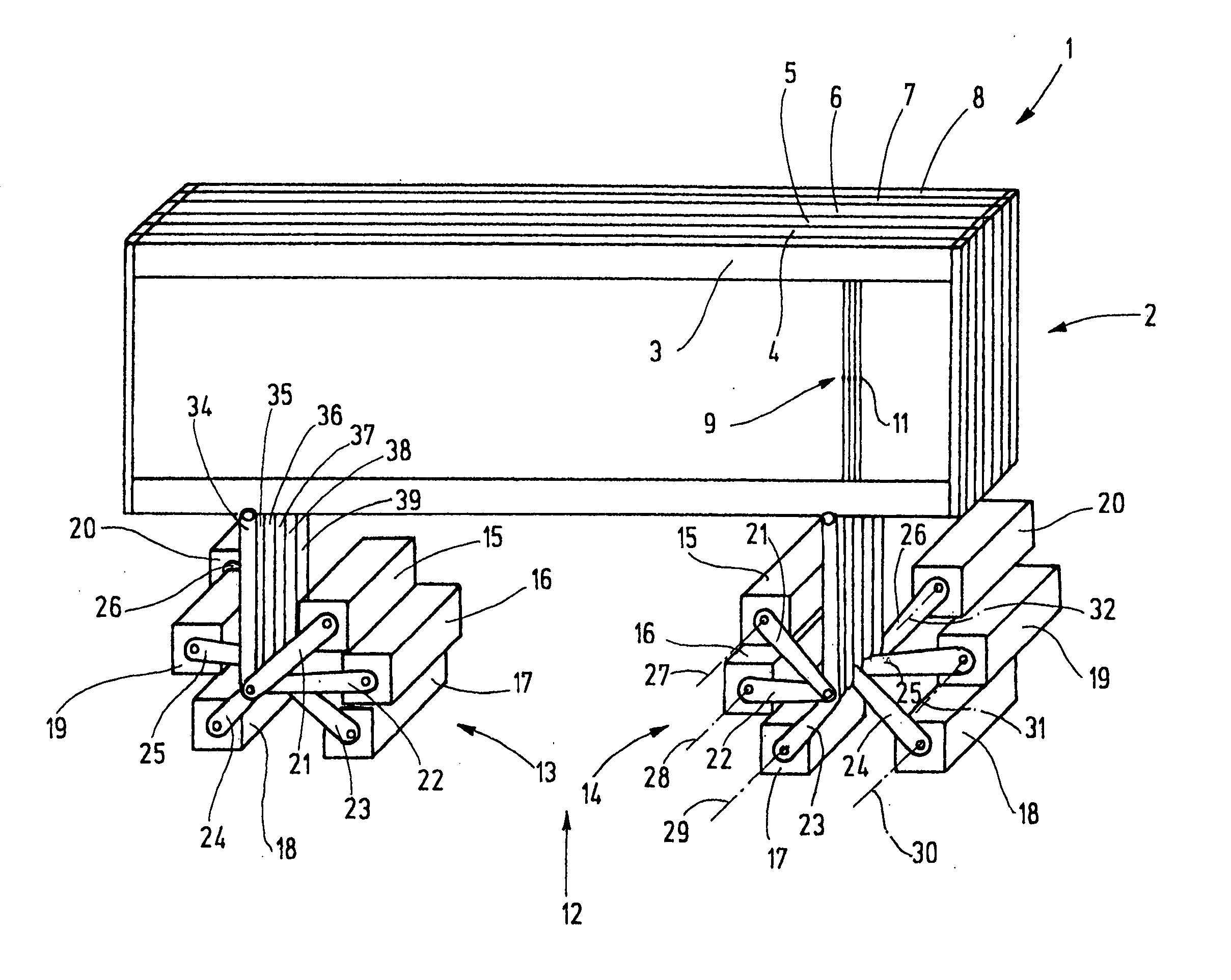
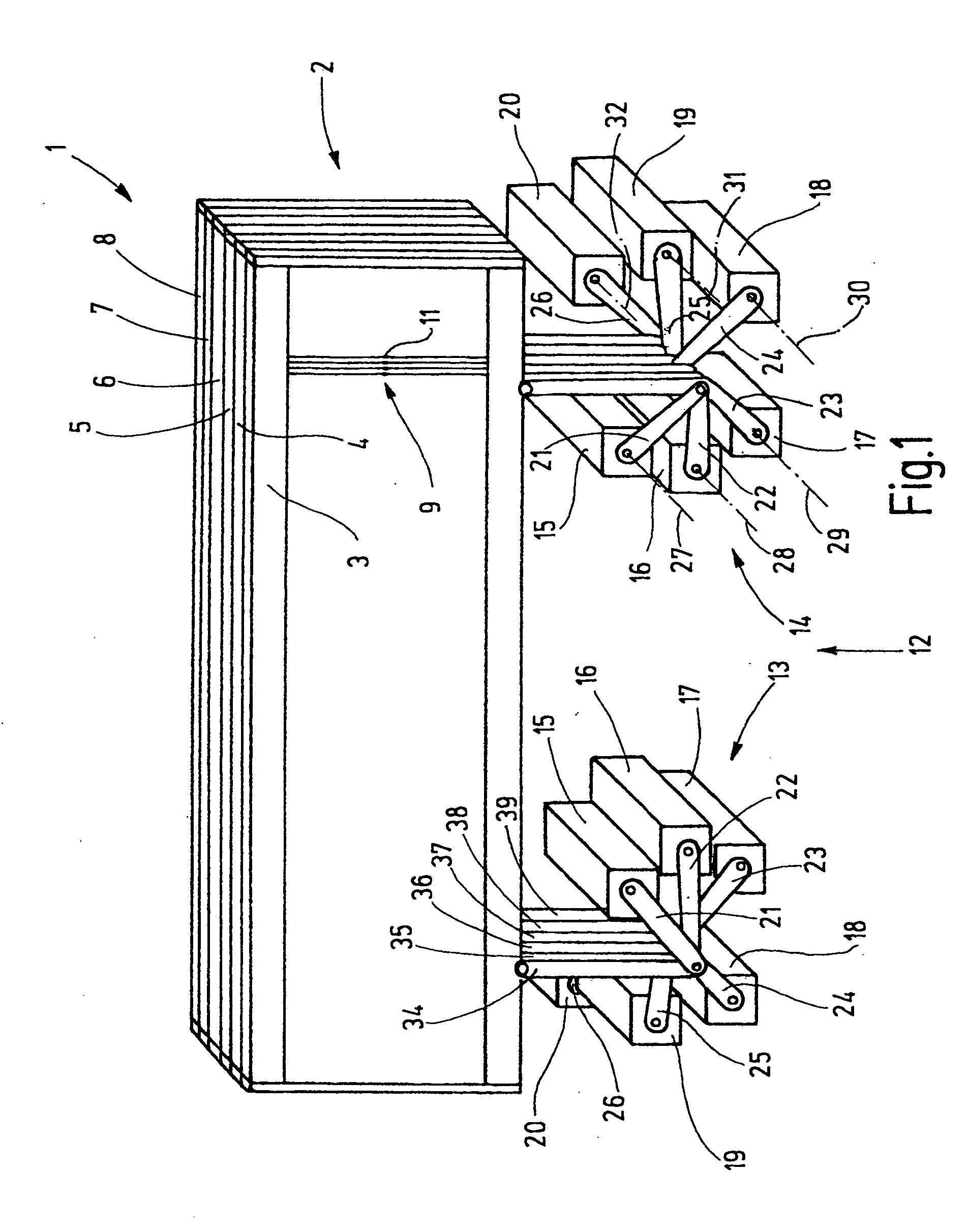
[0028] In FIG. 1, a shed forming device 1 is shown, to which twelve heddle shafts 2 belong. Of these, six heddle shafts 3 through 8 are shown in FIG. 1. The heddle shafts 2 are each formed by a rectangular frame with an upper and a lower, typically horizontally located, shaft rod. The ends of the shaft rods are joined together by so-called side struts. The heddle shafts 2 serve to guide and support heddles 9, whose ends are seated on heddle slide bars that are not shown further. The heddles 9 are low, flexible metal elements, each with at least one yarn eyelet 11 for guiding the warp yarn. The heddles 9 are preferably seated with some longitudinal play (vertical play) on the corresponding heddle slide bars. If a heddle shaft 3 through 8 is guided upward or downward (that is, is adjusted in the longitudinal direction of the heddles) while the other heddle shafts remain in the same place, a shed is created, into which a weft yarn can be inserted (weft insertion).

[0029] The heddle sha...


PUM


Abstract

A shed forming device (1) for a power loom has a plurality of heddle shafts, to which a drive mechanism with a plurality of servo motor groups (13, 14) is assigned. The servo motor groups are located below each of the heddle shafts (3 through 8), in each case as a cluster, and they are located with their pivot axes (27 through 32) on a circle, an ellipse, or a similar figure. They are also axially offset from one another. Each servo motor (15 through 20) is provided with a driven lever (21 through 26). The free ends of all the levers are located approximately at the center of the circle or ellipse or other figure of revolution. They are connected to the heddle shafts (3 through 8) via connecting rods (34 through 39) and form various angles with the connecting rods (34 through 39). The result is a drive mechanism with little inertia, low resilience, and little play. Very fast shaft motions can be attained in a controlled way.

Description

CROSS REFERENCE TO RELATED APPLICATION [0001] This application claims the priority of German Patent Application No. 10 2004 006 389.3, filed on Feb. 10, 2004, the subject matter of which, in its entirety, is incorporated herein by reference. FIELD OF THE INVENTION [0002] The invention relates to a shed forming device for a power loom. BACKGROUND OF THE INVENTION [0003] Power looms have a so-called shed forming device, which serves to guide warp yarns outward and upward or downward from the warp yarn plane in accordance with a binding pattern, so that the spread-apart warp yarns create what is known as a shed. A weft yarn is introduced into this shed (weft insertion). Shedding can be done for instance by means of so-called heddles, with one warp yarn passing through the eye of each heddle. The heddles are held on a frame that is called a heddle shaft. The heddle shaft must be moved up and down in rapid succession in accordance with the pace of operation of the power loom. As a rule, ...

Claims


Application Information

Patent Timeline
IPC IPC(8): D03C5/00D03D5/00D03C13/00
CPCD03C13/025D03C5/00
Inventor METTLER, FRANZ
Owner GROZ BECKERT KG
Why Eureka
Try Eureka