Device for connecting two elements having a substantially cylindrical or tubular shape

Inactive Publication Date: 2005-08-25
TECHMO ENTWICKLUNGS UND VERTRIEBS
View PDF4 Cites 2 Cited by
  • Summary
  • Abstract
  • Description
  • Claims
  • Application Information

AI Technical Summary

Benefits of technology

[0004] The present invention aims to provide a device for connecting two substantially rod- or tube-shaped elements of the initially defined kind, which enables the simple and reliable connection of two elements to be connected. Such a simple and reliable connection is to be feasible particularly under rough environmental conditions and aimed to reliably prevent any undesired detachment or separation of the elements to be connected, both in the axial direction and in the longitudinal direction of the elements to be connected as well as being readily or simply produced.
[0005] To solve these objects, a device of the initially defined kind is essentially characterized in that the partial region capable of being pressed in and / or shifted is delimited by a slot provided in the female end or sleeve, respectively, and delimiting in top view a particularly substantially U-shaped partial region capable of being pressed in. Such a, for instance, substantially U-shaped slot can be produced in the region of the female end, or a sleeve or bushing, respectively, by simple means and accordingly quickly, whereupon, after insertion or introduction of the male end, a connection of the elements to be connected is feasible by simply pressing or displacing or driving the partial region delimited by the slot into the complementary or corresponding depression or recess provided on the male end.
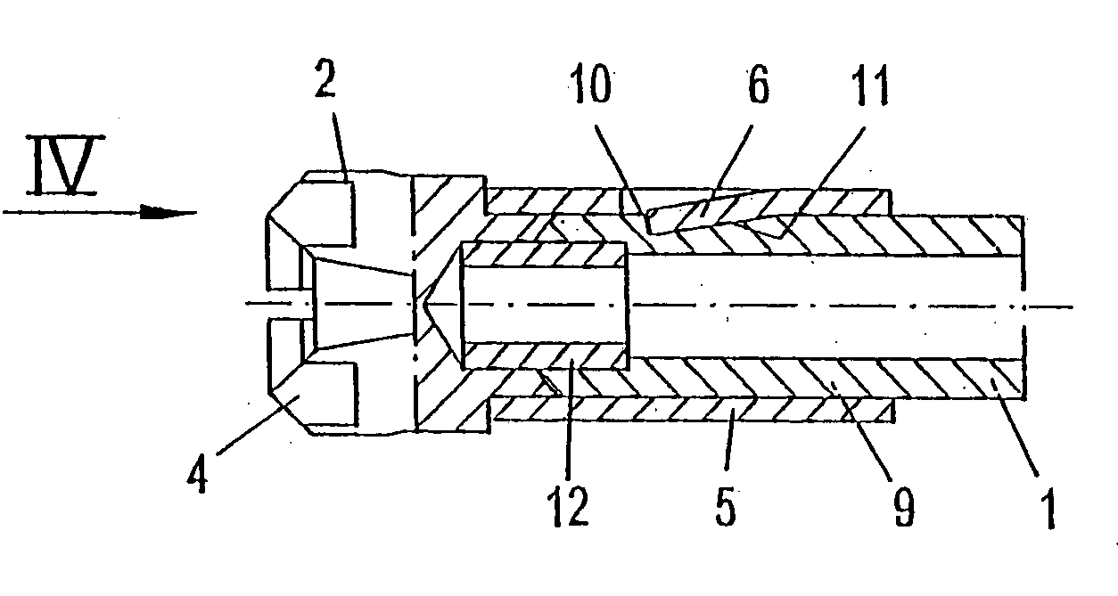
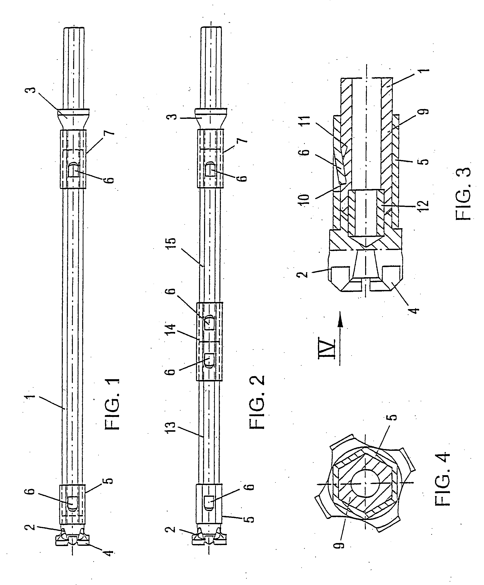
[0006] Due to the fact that according to the invention a partial region provided on the female end and capable of being shifted and / or pressed in engages in a complementary depression or recess provided on the male end of the second element of the connection to be assembled, and is received in said depression or recess in a substantially positive manner, a simple coupling or connection of the elements to be connected is ensured either directly via the female end into which the male end is immersed, or by the aid of an appropriate bushing or sleeve. The partial region capable of being pressed in or driven in engages in the respective recess provided on the female end, and any detachment or separation of the elements to be connected is reliably prevented in the axial direction and / or longitudinal direction by the arrangement of the insertable partial region or projection, respectively. Moreover, it is immediately apparent that the connection proposed according to the invention by the simple insertion, or fitting into each other, of the elements to be connected, or by the insertion of a male element into a bushing or sleeve, will be sufficient, whereupon, after the desired positioning in a relative axial position, a partial region capable of being pressed in or driven in is driven into the depression or recess of the female part, thus rapidly and safely providing the desired connection. In addition, the partial region provided according to the invention and capable of being shifted and / or pressed in not only ensures a reliable plug-type connection on mutually cooperating ends, but also enables the provision of an accordingly thin material thickness for maintaining the plug-type connection such that even small bore or borehole diameters may be envisaged. Compared with a thread connection, such a plug-type connection also ensures an enhanced force transmission, because accordingly large stop surfaces or reception surfaces can be provided between the individual elements of a plug-type connection, while only small abutment surfaces, for instance by line contacts, will be available with threads, particularly in the case of wear due to high stresses or strains.
[0009] For another particularly simple and hence cost-effective and time-saving configuration of the respective depression or recess provided on the male end, it is, moreover, proposed that the recess or depression provided on the male end is formed by a channel or groove extending substantially in the longitudinal direction of the elements to be connected, as in correspondence with a further preferred embodiment of the device according to the invention. As already indicated above, it is feasible by the device proposed according to the invention to provide a reliable securement substantially simple to produce, of rod- or tube-shaped elements to be connected, in the axial direction or longitudinal direction of these elements. If the elements are to be secured against a relative rotational movement too, or if a rotational movement is exerted on these elements, for instance when carrying out a drilling procedure, or if a rotational movement is to be transmitted from a driving means to a drilling tool via those elements such as, for instance, rod assembly elements, it is provided according to a further preferred embodiment, in order to obtain an appropriate rotational entrainment, that the male end and the female end or sleeve, respectively, are each designed to have a peripheral shape deviating from a circular shape, for instance a peripheral shape hexagonal in cross section. Such peripheral shapes deviating from a circular shape can also be produced in an accordingly simple and cost-effective manner with a snug fit so as to again ensure a simple connection by the simple introduction or insertion of a male end into a female end, or a sleeve or bushing forming an intermediate element, by subsequently pressing or displacing the respective partial regions into the respective recesses provided on the outer peripheries of the ends to be received. Since rod- or tube-shaped elements to be connected may optionally have comparatively high material cross sections, thus optionally rendering difficult the pressing in or driving in of the partial regions provided for the connection, or optionally requiring a high impact strain to do so, it is proposed according to another preferred embodiment that the partial region capable of being shifted and / or pressed in is designed to have a cross section reduced relative to the adjacent end regions. Such a reduced cross section allows for the reliable driving in or pressing in of the partial regions provided for the connection, while still affording a sufficiently high connection force or retention force against any unintentional detachment, particularly in the axial direction.

Problems solved by technology

Those known connections, in particular, involve the disadvantage that ends partially worked to fit snugly, of elements to be connected must each be inserted one into the other and rotated relative to each other, or generally moved, in order to enable a desired connection to be established.
It is immediately apparent that, for instance, such screw connections not only involve much time for manufacture, but also call for a high positioning accuracy, or the alignment of elements to be connected, in order to secure said connections, such an accurate positioning being difficult in some cases such as, for instance, the extension of drill rod assemblies or the like usually having great lengths.
Moreover, it is to be anticipated that the connection sites are subjected to accordingly high stresses, particularly after an extended period of use or use under rough environmental conditions, so that connections of this type will partially not be detachable again or only at high time and energy inputs.
Thus, it is, for instance, not feasible to provide drill bits for the production of bores or holes having small diameters, since it must inter alia be taken into consideration that the drill rod assembly must, as a rule, be designed to be hollow in order to enable the supply of flushing liquid into the region of the drill bit and / or the haulage of worked material and afford an accordingly large clear width.

Method used


Image

  • Device for connecting two elements having a substantially cylindrical or tubular shape
  • Device for connecting two elements having a substantially cylindrical or tubular shape

Examples


Embodiment Construction

[0019]FIG. 1 depicts a tubular rod assembly element 1 which, on the one hand, is to be fixable to, or connectable with, a drill bit or drilling tool 2 and, on the other hand, on its end facing away from the drill bit 2, is connected via a percussion element 3 with a driving means not illustrated in detail and acting on the percussion element 3 such as, for instance, a drive for rotary percussion drilling.

[0020] The connection of the drill rod assembly 1 both with the drill bit 2 and with the percussion element 3 is realized in the region of the drill bit 2 by immersing the rod assembly element 1 into a projection 5 projecting from the end facing away from the working surface of the drill bit 2, wherein the projection 5 comprises on its outer periphery a partial region 6 capable of being shifted and / or pressed in and entering a respective recess or groove provided on the outer periphery of the male end of the drill rod assembly 1, as is illustrated in more detail in FIG. 3.

[0021] I...


PUM


Abstract

In a device for connecting two substantially rod- or tube-shaped elements (1), for instance parts of a rod assembly of a drilling device and / or a rod assembly element (1) with a drill bit (2) or a drill head, wherein the elements to be connected are each designed to comprise a male end and a complementary female end or contiguous ends are each overlapped by a bushing or sleeve (5), it is provided that, on the female end or sleeve (5), respectively, at least one partial region (6) capable of being shifted towards the female end substantially in the radial direction of the connection, and / or pressed in, is engagingly fixed in a complementary recess or depression (10) provided on the male end (9), thus making available a connection between tube-shaped elements (1), which is easy to produce, particularly without requiring any mutual rotation of the elements (1) in order to obtain the connection.

Description

FIELD OF THE INVENTION [0001] The present invention relates to a device for connecting two substantially rod- or tube-shaped elements, for instance parts of a rod assembly of a drilling device and / or a rod assembly element with a drill bit or a drill head, wherein the elements to be connected are each designed to comprise a male end and a complementary female end or contiguous ends are each overlapped by a bushing or sleeve wherein on the female end or sleeve, respectively, at least one partial region capable of being shifted towards the female end substantially in the radial direction of the connection, and / or pressed in, is engagingly fixed in a complementary recess or depression provided on the male end. DESCRIPTION OF THE PRIOR ART [0002] Devices of such type can be taken for example from U.S. Pat. No. 5,304,012, WO 97 / 41377, U.S. Pat. No. 4,513,488 or FR 21 104 E. [0003] In the context of connecting substantially rod- or tube-shaped or cylindrical elements, various ways of conn...

Claims


Application Information

Patent Timeline
IPC IPC(8): E21B17/046F16D1/027F16D1/108
CPCE21B17/046F16D1/108F16D1/027
Inventor MOCIVNIK, JOSEFEGGER-MOCIVNIK, RENE
Owner TECHMO ENTWICKLUNGS UND VERTRIEBS
Why Eureka
Try Eureka