Anti-clog discharge spout

Active Publication Date: 2005-08-25
SILGAN DISPENSING SYST CORP
View PDF16 Cites 5 Cited by
  • Summary
  • Abstract
  • Description
  • Claims
  • Application Information

AI Technical Summary

Benefits of technology

[0010] The invention solves the problems and overcomes the drawbacks and deficiencies of prior art anti-clog plunger head designs by providing in combination a manually actuated pump s

Problems solved by technology

For example, extending a protrusion or the like into the orifice from the outer surface of the orifice cup for anti-clogging purposes, could over time distort the orifice and thereby adversely affect the quality of spray through the orifice.
The solutions which utilize a pivotable discharge nozzle have drawbacks in that the nozzle can become damaged after repeated pivoting thereof, and th

Method used


Image

  • Anti-clog discharge spout
  • Anti-clog discharge spout
  • Anti-clog discharge spout

Examples


Embodiment Construction

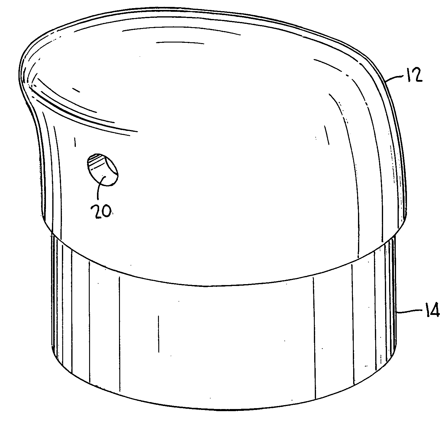
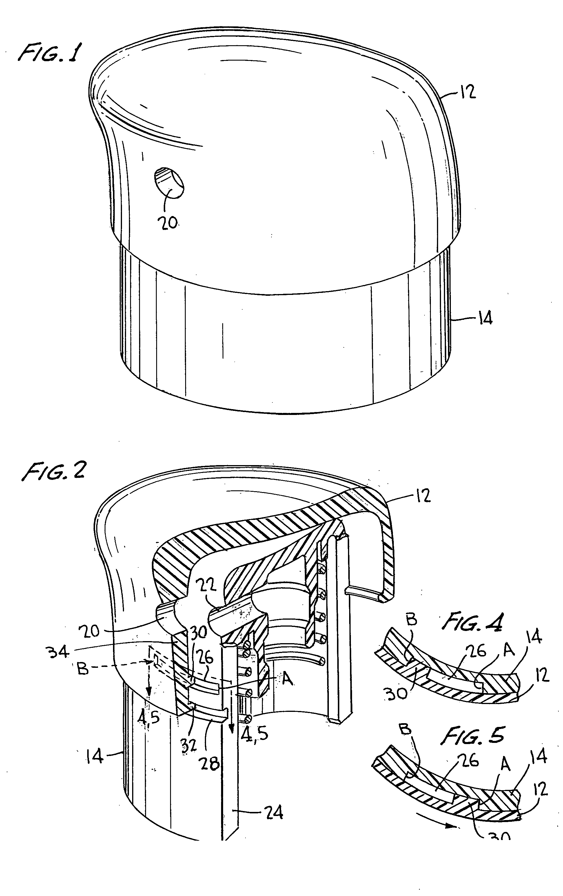
[0024] Referring now to the drawings wherein like reference numerals designate corresponding parts throughout the several views, FIGS. 1-5 illustrate a manually actuated pump sprayer according to the present invention, generally designated 10.

[0025] As shown in FIGS. 1-5, pump sprayer 10 of the present invention is of the precompression variety and includes features and elements similar to the sprayers disclosed in U.S. Pat. Nos. 5,785,208, 6,158,625, 6,223,951, and 6,257,451, which are commonly owned herewith and the respective disclosures of which are incorporated in their entirety by reference. As illustrated, pump sprayer 10 may generally include an overcap 12 operatively connected to plunger head 14 which is spring biased and axially reciprocable relative to container closure 16 for discharging liquid product within a container (not shown). A dip tube (not shown) may be disposed within the container as is known in the art, and is operatively connected to an axially reciprocabl...


PUM


Abstract

A manually actuated pump sprayer adapted to be mounted on a container of liquid to be sprayed upon pump actuation is provided, and includes a plunger head having a side wall containing a discharge orifice. The plunger head may be reciprocable relative to the pump sprayer. An overcap may be independently rotatably disposed on the plunger head, and include a side wall overlying the discharge orifice in a condition of non-use. The side wall may include an opening disposable in alignment with the discharge orifice upon rotation of the overcap relative to the plunger head. A container closure may be provided for affixing the plunger head and the overcap relative to the container. The plunger head may be axially reciprocable relative to the container closure and may otherwise be locked relative to the container closure when in first and second orientations.

Description

BACKGROUND OF INVENTION [0001] a. Field of Invention [0002] The invention relates generally to manually actuated pump sprayers, and more particularly to such sprayers having means for preventing clogging of the discharge orifice due to product drying at the orifice and means for locking the plunger head for preventing plunger reciprocation. [0003] b. Description of Related Art [0004] Prior art pumps of the general type are known as having some type of anti-clog means such as the provision of a small projection extending into the orifice opening from outside the orifice cup. The projection is provided on a cover overlying the plunger head and shiftable relatively thereto for both sealing the orifice closed and for breaking away any accumulated dried product which may have accumulated on the outside surface of the orifice cup. [0005] Alternatively, the discharge nozzle itself may be pivotable out of alignment from the discharge passage for protection against pollution, as well as for ...

Claims


Application Information

Patent Timeline
IPC IPC(8): B05B11/00B65D83/76B05B15/02B65D47/34F04B9/14F04B33/00
CPCB05B11/0027B05B15/0208B05B15/02B05B11/3059B05B15/50B05B15/52B05B11/1059F04B9/14F04B33/00
Inventor COSTA, LLUISPIETROWSKI, DARIA
Owner SILGAN DISPENSING SYST CORP
Why Eureka
Try Eureka