
Convergence system for a projection display system

Inactive Publication Date: 2005-08-25
BARCO NV
View PDF5 Cites 18 Cited by
  • Summary
  • Abstract
  • Description
  • Claims
  • Application Information

AI Technical Summary

Benefits of technology

[0015] It is an advantage of the present invention that the convergence system behaves as monolithic in its construction.
[0016] It is another advantage of the convergence system that is highly isotropic.
[0017] Furthermore, it is a specific advantage of the present invention that the convergence system has a good resistance to thermal stress.
[0018] It is another advantage of the present invention that the convergence system is resistant to humidity.
[0019] Moreover, it is an advantage of the current invention that the convergence system suffers little or less from hysteresis.
[0020] Although there has been constant improvement, change and evolution of devices in this field, the present concepts are believed to represent substantial new and novel improvements, including departures from prior practices, resulting in the provision of more efficient, stable and reliable devices of this nature.

Problems solved by technology

Nevertheless, none of the above systems describes a convergence system having an image quality that is practically insensitive to environmental factors due to an optimum construction and assembly of the convergence system.

Method used


Image

  • Convergence system for a projection display system
  • Convergence system for a projection display system
  • Convergence system for a projection display system

Examples


first embodiment

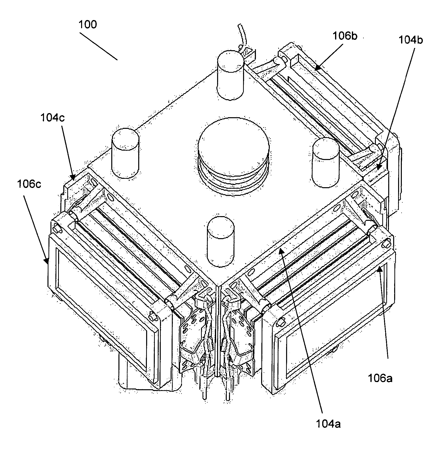
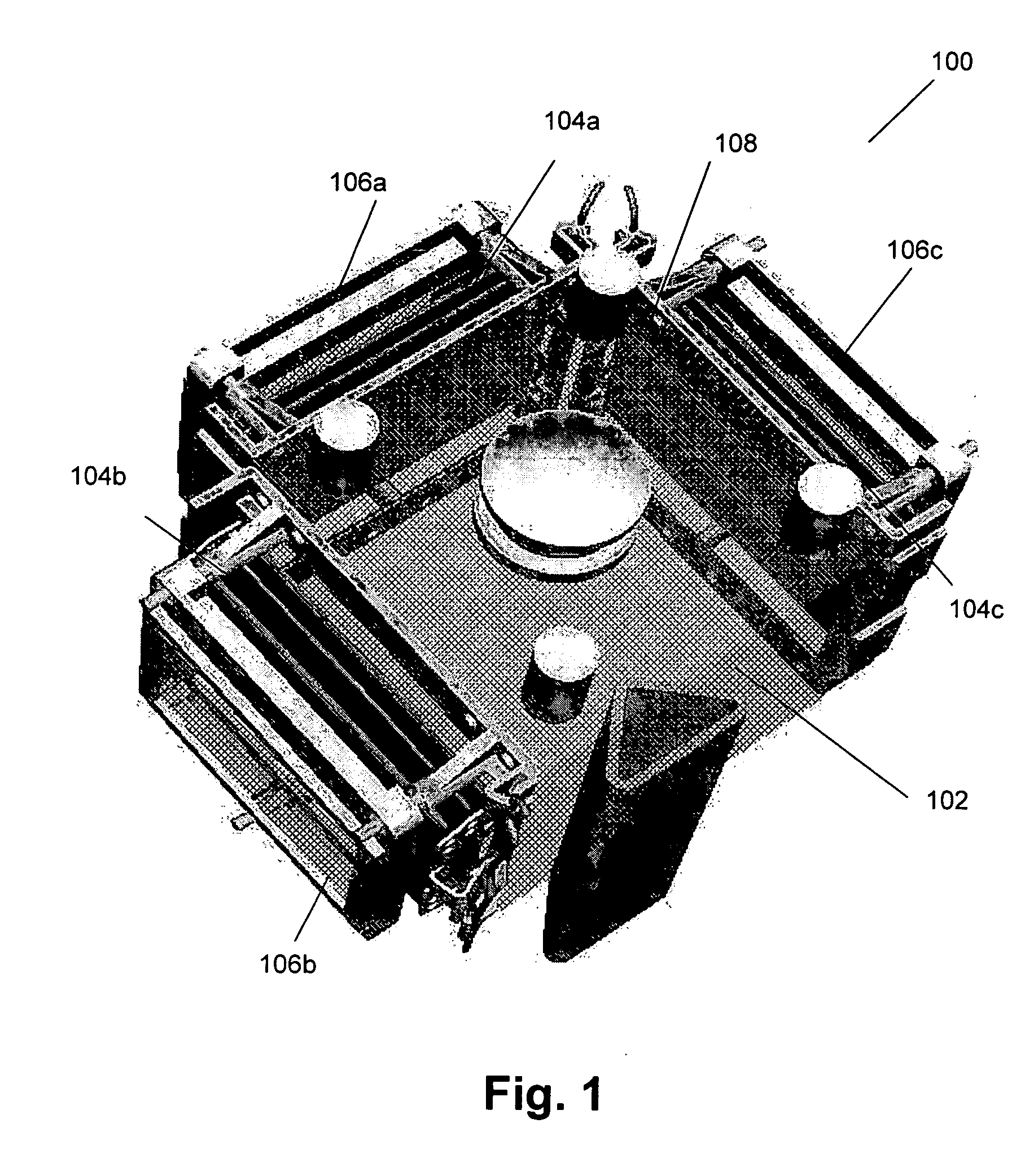
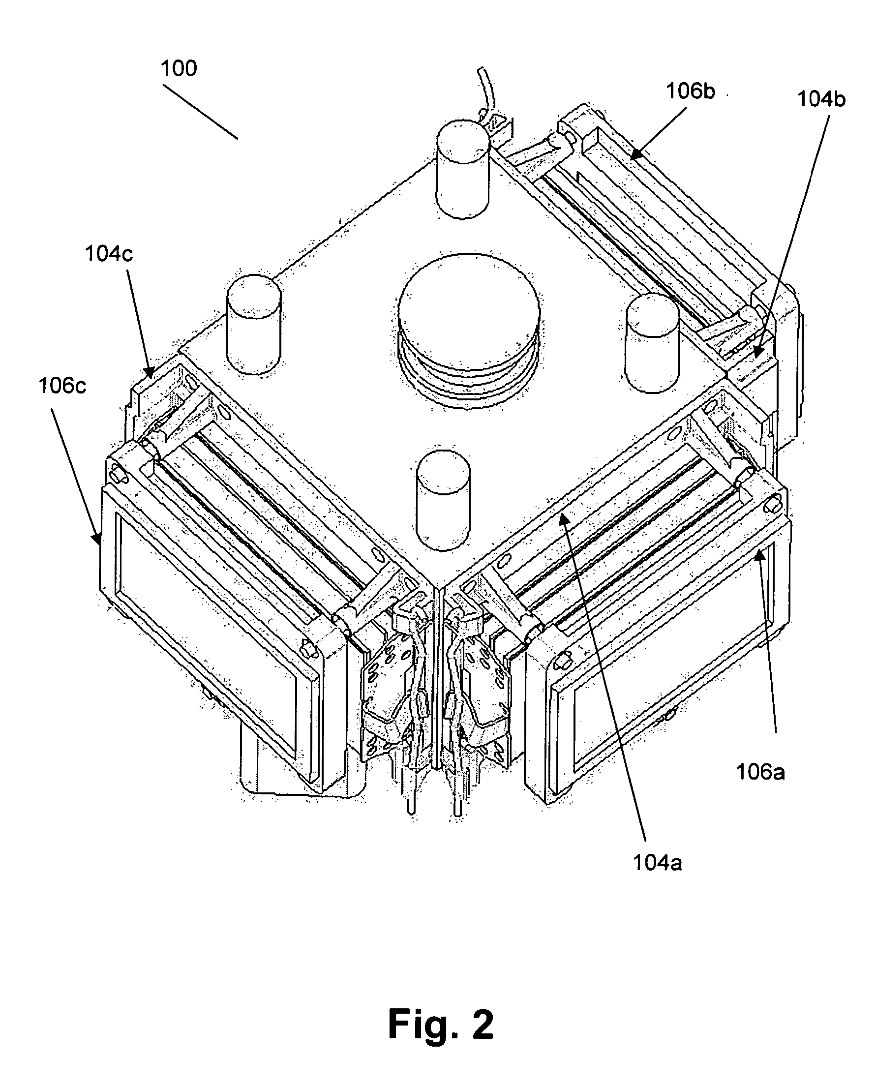
[0038] Similarly, it is to be noticed that the term “coupled”, also used in the claims, should not be interpreted as being restricted to direct connections only. Thus, the scope of the expression “a device A coupled to a device B” should not be limited to devices or systems wherein an output of device A is directly connected to an input of device B. It means that there exists a path between an output of A and an input of B which may be a path including other devices or means. FIG. 1 shows a convergence system according to the present invention. The convergence system 100 comprises an X-cube 102, three (or more) single intermediate parts 104 for three (or more) different colors or color ranges and light modulating means 106 for each of these three (or more) different colors. The X-cube 102 is a dichroic prism which allows recombination of three outgoing beams having a different color or color range into one beam. Some prisms however act as splitting and recombining mirrors at the sam...

second embodiment

[0046] obtaining symmetrical behaviour on the screen is by mirroring parts that are not symmetrical for a specific color. For example, in the system shown in FIG. 7, the asymmetric part or all parts of the intermediate part that is positioned opposite to the entrance and / or exit side for the white beam, will be mirrored against the asymmetric part of the intermediate parts adjacent the entrance and exit side for the white beam. This is because a color light beam that is modulated by the intermediate part opposite to the entrance and / or exit side for the white beam is not reflected and thus not mirrored anymore by the X-cube dichroic mirror, while the color light beams modulated by intermediate parts adjacent to the entrance and / or exit side for the white beam are reflected and thus mirrored in the x-cube dichroic mirror, thereby providing a mirrored image on the screen. If thus an asymmetric shift occurs in the light modulating means due to environmental effects on asymmetric parts ...


PUM


Abstract

A convergence system 100 comprises a dichroic prism 102 for splitting and / or recombining light beams, intermediate parts 104a, 104b, 104c and a light modulator 106a, 106b, 106c for every color beam. The intermediate parts 104a, 104b, 104c are constructed such that the convergence system has an improved resistance for variations in environmental effects like temperature and humidity. The intermediate parts 104a, 104b, 104c are constructed such that the convergence system has a high stability, a large degree of monolithicy and a high movement isotropy. When used in a projection display system, the projection display system has a high degree of color uniformity.

Description

TECHNICAL FILED OF THE INVENTION [0001] The present invention relates to a convergence system involving apparatus and methods for splitting and recombining color light beams in color projection systems. More specifically, a convergence system involving apparatus and methods for splitting, modulating and recombining of color light beams is described for producing high quality color images. BACKGROUND OF THE INVENTION [0002] Large-screen, high-brightness electronic projection display apparatuses serve different broad areas of application such as e.g. electronic presentations for business, education, advertising, entertainment, simulation and status and information. [0003] Electronic projection display apparatuses can have several designs. One of the optical designs often used, comprises mirrors that split an incoming light beam, which typically is a white light beam, in three different colour beams, typically a red, green and blue color beam, modulates the different colour beams with ...

Claims


Application Information

Patent Timeline
IPC IPC(8): H04N9/28
CPCH04N9/317H04N9/28
Inventor HALSBERGHE, BRECHTDEN BOSSCHE, BART VANDE VELDE, CINDY VANARTEEL, JAN LEO
Owner BARCO NV
Learn More