
Photoluminescent Sheet

a technology of photoluminescent sheets and sheets, applied in the field of photoluminescent sheets, can solve the problems of weakened eyesight, frequent replacement, high power consumption and heat emission, etc., and achieve the effect of increasing the resistance to heat and humidity

Active Publication Date: 2009-08-27
SUZHOU LEKIN SEMICON CO LTD
View PDF15 Cites 48 Cited by
  • Summary
  • Abstract
  • Description
  • Claims
  • Application Information

AI Technical Summary

Benefits of technology

[0009]An aspect of the present invention aims to provide a photoluminescent sheet which can implement white light using inexpensive blue LED's, and which has high resistance to heat, brittleness, and humidity.
[0020]Meanwhile, a protective film may be attached to a surface of the matrix resin layer. The protective film is a transparent layer, which protects the matrix resin layer for increased resistance to heat and humidity.
[0021]The surface of the protective film may have uneven levels. This is for the functions of diffusion and anti-wetting. Minute balls for preventing wetting may be attached to the surface of the protective film, to prevent wetting when another sheet is placed in contact with the photoluminescent sheet.

Problems solved by technology

However, incandescent light bulbs and fluorescent tubes entail high power consumption and heat emission, and due to their short durability of about six months, there is a need for frequent replacement.
In addition, fluorescent tubes use mercury, which is a carcinogenic substance, and may thus be subject to regulations, and when fluorescent tubes are used for direct lighting, the flickering of the light source may cause weakened eyesight.
There are also several other drawbacks, including the requirement of large installation spaces, and difficulties in installation and color adjustment, etc.
However, ultraviolet LED's and white LED's not only require complicated fabricating processes, but also incur much higher fabricating costs, such that their use is substantially limited.
However, since the conventional photoluminescent sheet is formed by kneading an inorganic phosphor with a thermoplastic resin as the matrix resin using a two-axis extruder, it is difficult to obtain uniform mixing of the phosphor in the resin sheet, which causes severe non-uniformity in luminance and color coordinates.
Also, since the conventional color conversion sheet was fabricated by extrusion molding a colored pellet, in which a matrix resin and a phosphor were kneaded, identical extrusion-molding conditions produced only identical forms of color conversion sheet, to result in low applicability.
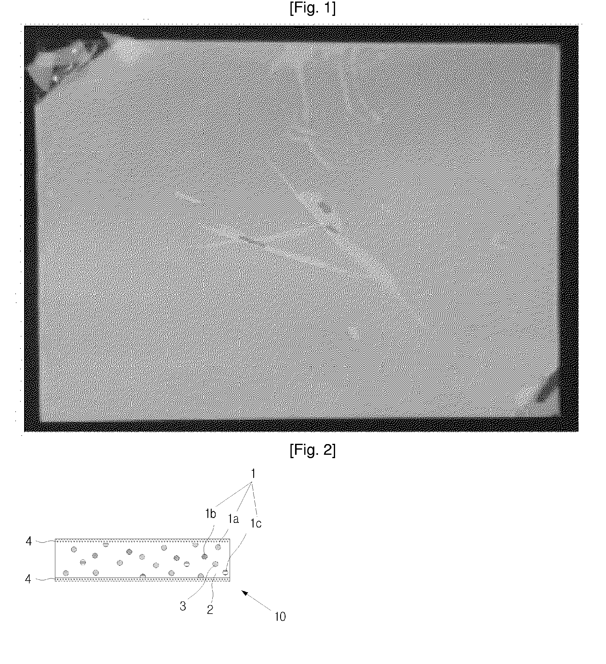
Furthermore, thermoplastic resins such as polycarbonate or polymethylmethacrylate resin, etc., used for the matrix resin were limited in application, because they are high in brittleness and may easily break, as in the photograph of FIG. 1, and because they are low in heat-resistance (120° C. or lower) and may easily undergo plastic deformation at high temperatures.

Method used


Image

  • Photoluminescent Sheet
  • Photoluminescent Sheet
  • Photoluminescent Sheet

Examples


Embodiment Construction

[0045]Embodiments of the invention will be described below in more detail, with reference to the accompanying drawings, where the same reference numerals are used for the same or corresponding components, and redundant descriptions are omitted.

[0046]FIG. 2 is a cross-sectional view of a photoluminescent sheet according to a first disclosed embodiment of the present invention. In FIG. 2 are illustrated a yellow phosphor 1a, red phosphor 1b, green phosphor 1c, phosphor 1, matrix resin layer 2, diffusing agent 3, protective film 4, and photoluminescent sheet 10.

[0047]The photoluminescent sheet 10 shown in FIG. 2 has the function of transforming the light of a blue LED, having a wavelength of 400 nm˜500 nm, into white light. Basically, it has the form of a thin matrix resin layer 2 having a phosphor dispersed within.

[0048]Although it is not shown in FIG. 2, a curing agent and an additive may be included inside the matrix resin layer 2. The curing agent is used for curing liquid thermose...


PUM

PropertyMeasurementUnit
temperaturesaaaaaaaaaa
wavelengthaaaaaaaaaa
temperatureaaaaaaaaaa

Abstract

A photoluminescent sheet is disclosed. A photoluminescent sheet that includes a matrix resin layer, which is a thermosetting resin; a phosphor, which is included in the matrix resin layer and which converts the wavelength of light emitted from a blue LED; a curing agent, which is included in the matrix resin layer and which cures liquid thermosetting resin; and an additive, which is included in the matrix resin layer and which disperses the phosphor uniformly within the matrix resin layer, can implement white light from light having wavelengths corresponding to blue color.

Description

TECHNICAL FIELD[0001]The present invention relates to a photoluminescent sheet, more particularly, to a photoluminescent sheet capable of implementing white light from the blue light of an LED (light emitting diode).BACKGROUND ART[0002]Various types of lighting equipment are used for providing light in the nighttime or in an indoor space and for spotlighting objects. Such lighting equipment provides light by receiving electrical energy from an electrical power source and converting it to light energy, where incandescent light bulbs or fluorescent tubes are generally used. However, incandescent light bulbs and fluorescent tubes entail high power consumption and heat emission, and due to their short durability of about six months, there is a need for frequent replacement.[0003]In addition, fluorescent tubes use mercury, which is a carcinogenic substance, and may thus be subject to regulations, and when fluorescent tubes are used for direct lighting, the flickering of the light source ...

Claims


Application Information

Patent Timeline
Patent Type & Authority Applications(United States)
IPC IPC(8): C09K11/02
CPCB32B27/08C09K11/02C09K11/7774Y02B20/181B32B27/18Y10T428/2495B32B27/283B32B27/365B32B2307/306B32B2307/422B32B2457/00B32B27/26Y10T428/31855Y10T428/31507Y10T428/31786Y10T428/31938Y10T428/31663Y02B20/00E01C15/00E01C11/225
Inventor SOHN, CHOONG-YONGAHN, YOUNG-JOOKO, YOUNG-WOOK
Owner SUZHOU LEKIN SEMICON CO LTD
Learn More