Wavelength selectivity enabling subject monitoring outside the subject's field of view

a selectivity and subject technology, applied in the field of wavelength selectivity enabling subjects, can solve problems such as reducing the field of view of drivers

Active Publication Date: 2005-08-25
AVAGO TECH INT SALES PTE LTD
View PDF11 Cites 18 Cited by
  • Summary
  • Abstract
  • Description
  • Claims
  • Application Information

AI Technical Summary

Benefits of technology

[0007] For a system specifically designed for a motor vehicle, the windshield may include conventional coatings for achieving desired optical properties, but at least a portion of the windshield includes a coating which defines a dichroic mirror which is generally transparent to visible light and substantially reflective with respect to a driver-detection range of wavelengths. A detector is positioned to receive reflected light within the range of wavelengths following reflection from the windshield. The detector is positioned outside any line of sight from the driver to the windshield. The output of the detector is coupled to a processor for determining information regarding the driver. The system may be dedicated to monitoring the alertness of the driver, may be dedicated to verifying the identity of the driver, or may serve a number of purposes. The detector may be embedded within the dashboard of the motor vehicle in order to completely eliminate any possibility of obstructing the view of a driver. Similarly, any light sources that are a part of the system may be embedded within the dashboard or may be located in other positions that do not affect the field of view. In the applications involving driver monitoring, the optical member has a unitary magnification and the view of the driver is not affected by the output of the driver (i.e., the driver's vision remains independent of the detector output). The invention may be used in an automobile, airplane or other vehicle that is driven by means of a motor.

Problems solved by technology

A low profile system having an illumination source and a suitable camera may be used, but the system will nevertheless reduce the field of view of the driver.

Method used


Image

  • Wavelength selectivity enabling subject monitoring outside the subject's field of view
  • Wavelength selectivity enabling subject monitoring outside the subject's field of view
  • Wavelength selectivity enabling subject monitoring outside the subject's field of view

Examples


Embodiment Construction

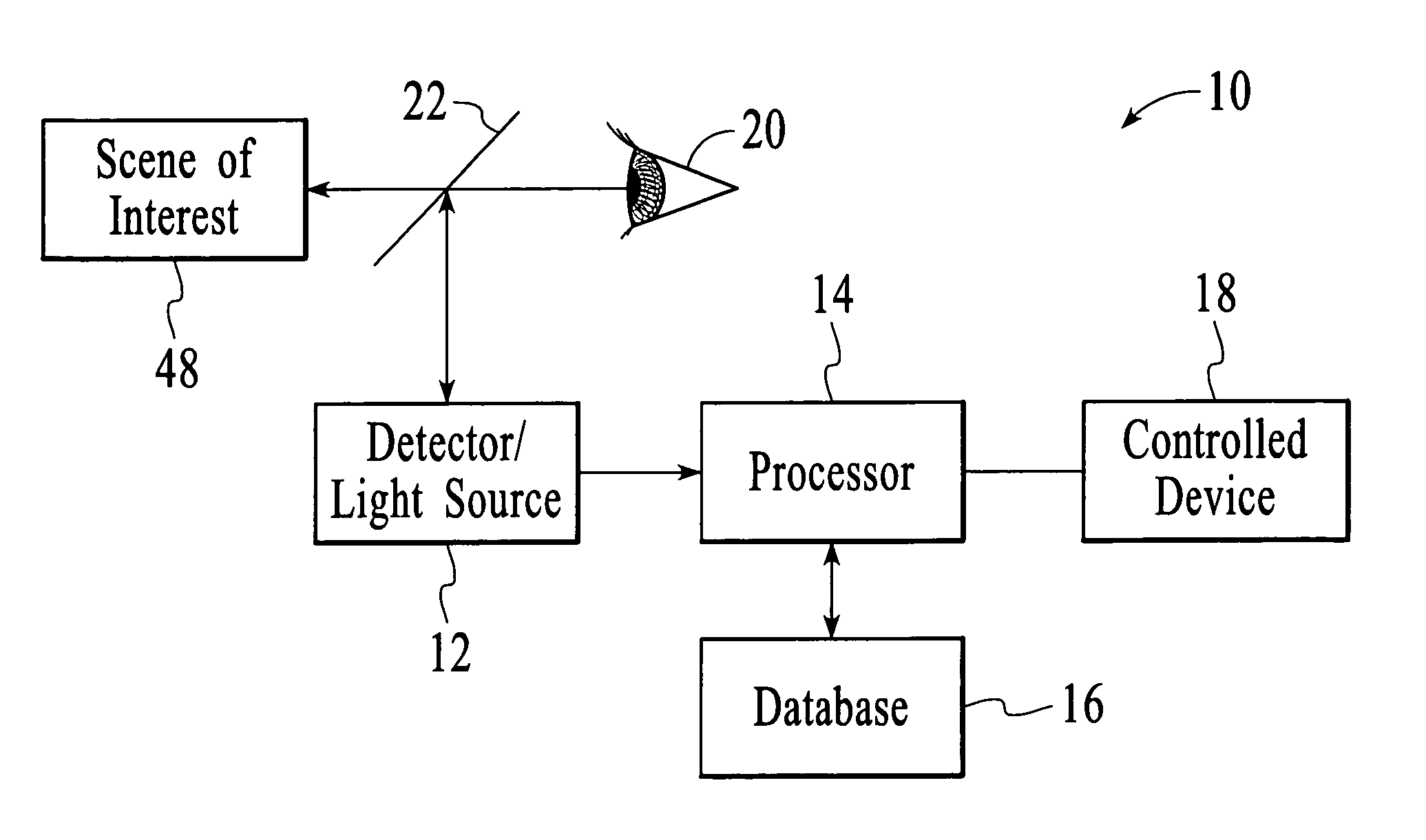
[0016] With reference to FIG. 1, a system 10 that utilizes wavelength selectivity to enable a subject to be monitored without obstructing the field of view of the subject is shown as including a detector / light source 12, a processor 14, a database 16, and a controlled device 18. In the embodiment of FIG. 1, it is the eye 20 of the subject that is detected for the purpose of acquiring information regarding the subject and it is an optical member 22 that provides the desired wavelength selectivity. The optical member is a dichroic mirror that is generally transmissive with respect to visible light and substantially reflective with respect to a particular detection wavelength, such as infrared (IR) light. By “substantially reflective,” what is meant herein is that the detection wavelength is sufficiently reflected by the dichroic mirror to allow the detector to acquire reliable information regarding the subject. Thus, less than 100% of the energy at the detection wavelength need be ref...


PUM


Abstract

A detection system for monitoring a subject remains outside the normal field of view of the subject by using a wavelength selective optical member. In one application, an eye of a driver is repeatedly or continuously illuminated and imaged without effect on the field of view of the driver. A dichroic mirror may be used to provide the wavelength selectivity. For the application in which the system is used for a motor vehicle, such as an automobile, the dichroic mirror may be achieved by coating a portion or all of the windshield so as to pass visible light, while reflecting detection light. Other applications of the detection system include monitoring a subject engaged in a person-to-person interaction, wherein a dichroic mirror is defined by a divider between the two persons.

Description

BACKGROUND ART [0001] In a variety of different applications, it is of interest to acquire information regarding an individual without diverting the attention of the person. In one such application, a system may be used to monitor the perceived drowsiness of a driver of a motor vehicle, such as an automobile, train, airplane and the like. There are also security applications, such as the verification of the identity of a driver or the identity of a patron of a business (e.g., a bank). One technique for monitoring drowsiness, verifying identity, or determining other individual-specific information is to acquire data directly relating to the eyes of a person. Images of a person's pupil may be used in the same manner as a fingerprint. The degree or the length of time that the eyes of a person are open or closed may be used as an indication of a level of drowsiness of the person. [0002] Concerns with known approaches to acquiring the data include minimizing the distraction to the indivi...

Claims


Application Information

Patent Timeline
Patent Type & Authority Applications(United States)
IPC IPC(8): A61B5/18G02B26/02G02B27/00G02B27/01G08B21/06
CPCA61B5/18G02B27/0093G08B21/06G02B27/0101G02B2027/0138G02B27/01
Inventor WENSTRAND, JOHN S.
Owner AVAGO TECH INT SALES PTE LTD
Why Eureka
Try Eureka