
Parametric sound system with lower sideband

a sound system and sideband technology, applied in the field of parametric loudspeakers, can solve the problems of inability to achieve parametric efficiency, inability to achieve distortion reduction processing, and inability to achieve the desired output and parametric efficiency of flat response transducer systems

Inactive Publication Date: 2005-08-25
AMERICAN TECH
View PDF8 Cites 12 Cited by
  • Summary
  • Abstract
  • Description
  • Claims
  • Application Information

AI Technical Summary

Problems solved by technology

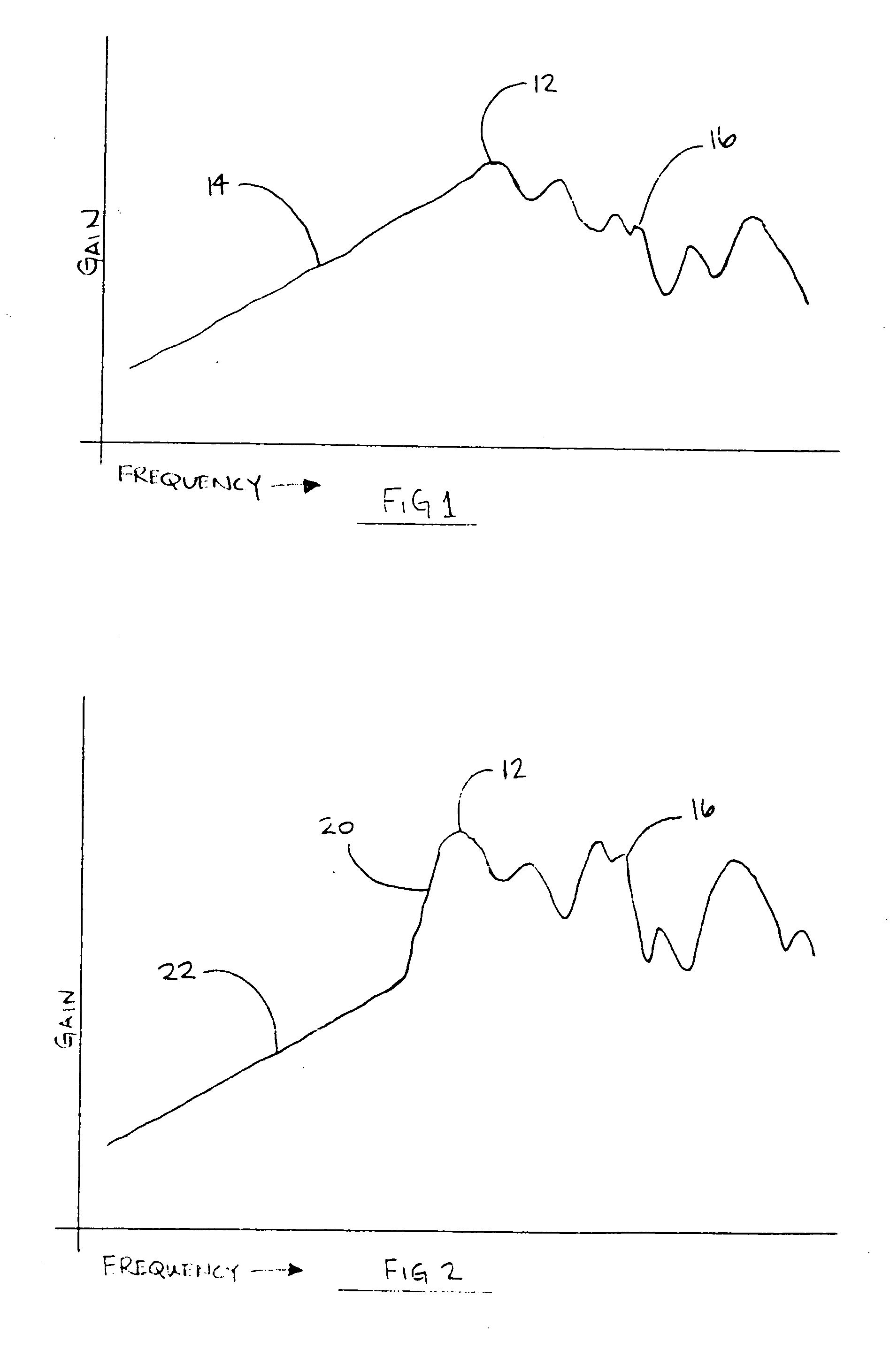
If the frequency response of the transducer is not generally flat over at least a 40 kHz range, the upper side band (USB) and the lower sideband (LSB) will not be symmetrical, and this makes distortion reduction processing difficult.
This situation is difficult to realize, so even a transducer with a smooth frequency response peak will not be linearly symmetrical above and below the resonance frequency of the transducer or carrier frequency.
Moreover, flat response transducer systems are generally too low in efficiency to generate desired output and parametric efficiency.
Those skilled in the art have shown that applying a square root function to the DSB signal in a parametric system can theoretically produce a low distortion system but at the cost of infinite system and transducer bandwidth.
It is not practical to produce a device that has an infinite bandwidth capability.
Further, the implementation of any significant bandwidth means that the inaudible ultrasonic primary frequencies can extend down into the audible range on the lower sideband and cause new distortion which may be as bad as the distortion eliminated by the square root pre-processing system.
Therefore, the theoretically ideal square rooted DSB system cannot be fully realized with prior art approaches.
Another problem inherent to parametric loudspeaker systems is that as the frequency and / or intensity of the ultrasonic carrier is increased to allow room in the inaudible range for the lower sidebands and to achieve reasonable conversion levels in the audible range, the air can be driven to saturation.
As a result, the saturation limit is easily reached and the overall efficiency of the system suffers.
These excessive and undesirable types of distortion affect the practical or commercial use of the uncompensated parametric arrays or even square-rooted compensation schemes in high fidelity applications.

Method used


Image

  • Parametric sound system with lower sideband
  • Parametric sound system with lower sideband
  • Parametric sound system with lower sideband

Examples


Embodiment Construction

[0016] Reference will now be made to the drawings in which the various elements of the present invention will be given numerical designations and in which the invention will be discussed so as to enable one skilled in the art to make and use the invention. It is to be understood that the following description is only exemplary of certain embodiments of the present invention, and should not be viewed as narrowing the claims which follow.

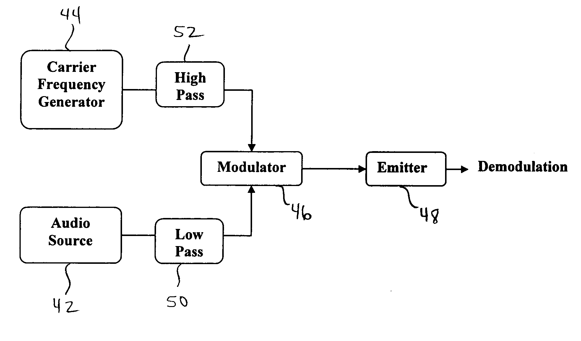
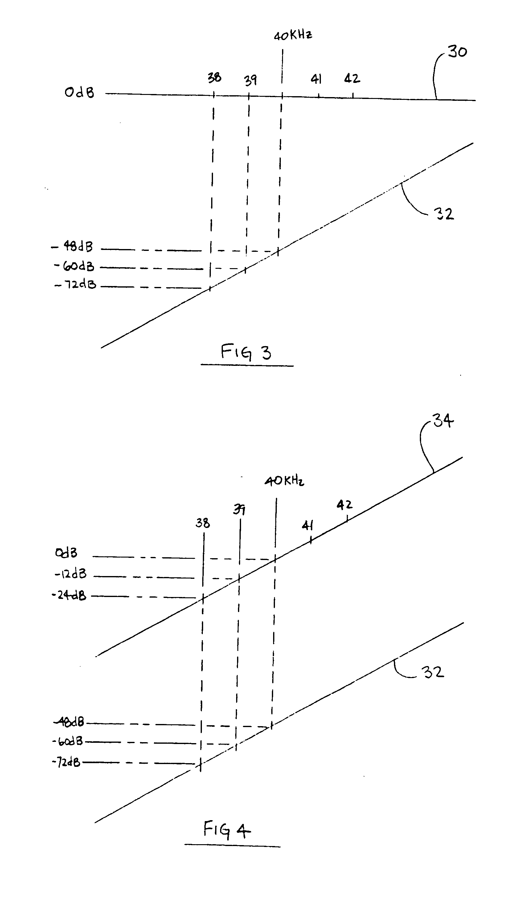
[0017] The present invention is a system and method for providing a parametric loudspeaker system with greater output for a parametric array with significantly less distortion than with previous systems. This is realized in part by the attenuation of energy at frequencies below the carrier frequency that may approach the audio range and cause distortion of the program material. In the present system, an incoming audio signal is modulated onto a higher ultrasonic carrier frequency to create a modulated signal. This modulated signal is then passed thro...


PUM


Abstract

This invention provides a parametric loudspeaker system, with a carrier frequency generator to produce a carrier frequency. A modulator receives an audio signal and modulates it onto the carrier frequency, producing a modulated signal. This modulation creates at least one sideband signal that is divergent from the carrier frequency by the frequency value of the audio signal. Additionally, the sideband signal is created such that its frequency value is lower than the frequency of the carrier.

Description

[0001] This application claims priority to and is a continuation-in-part of U.S. patent application Ser. No. 09 / 384,084 filed on Aug. 26, 2003, now registered U.S. Pat. No. 6,584,205, U.S. patent application Ser. No. 10 / 393,893 filed on Mar. 21, 2003, U.S. patent application Ser. No. 09 / 430,801 filed on Oct. 29, 1999, and U.S. Provisional Application No. 60 / 538,013 filed on Jan. 20, 2004. FIELD OF THE INVENTION [0002] This invention relates to parametric loudspeakers for generating audible output. BACKGROUND [0003] A parametric array in air results from the introduction of sufficiently intense, audio modulated ultrasonic signals into an air column. Self demodulation, or down-conversion, occurs along the air column resulting in an audible acoustic signal. This process occurs because of the known physical principle that when two sound waves with different frequencies are radiated simultaneously in the same medium, a modulated waveform including the sum and difference of the two freque...

Claims


Application Information

Patent Timeline
Patent Type & Authority Applications(United States)
IPC IPC(8): H04R3/00H04R17/00
CPCH04R3/00H04R2217/03H04R17/00
Inventor CROFT, JAMES J. III
Owner AMERICAN TECH
Learn More