Fan assembly and method

a technology of fan assembly and fan body, which is applied in the direction of machines/engines, stators, liquid fuel engines, etc., can solve the problems of less desirable, inefficient fans that require a different rotor geometry, and consume more power

a technology of fan assembly and fan body, which is applied in the direction of machines/engines, stators, liquid fuel engines, etc., can solve the problems of less desirable, inefficient fans that require a different rotor geometry, and consume more power

US20050186070A1Inactive Publication Date: 2005-08-25REVCOR

Image

  • Fan assembly and method
  • Fan assembly and method
  • Fan assembly and method

Examples


Embodiment Construction

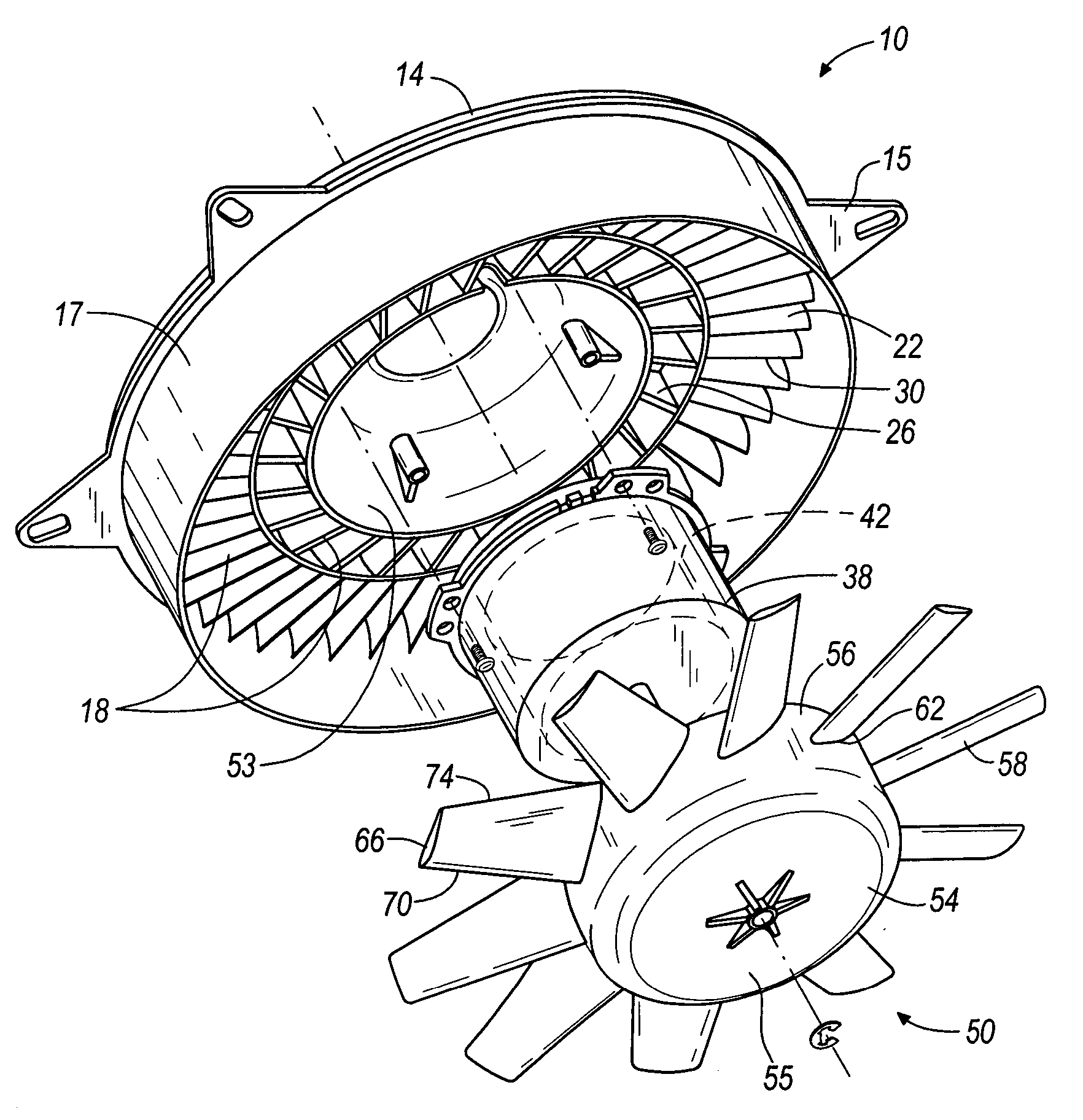
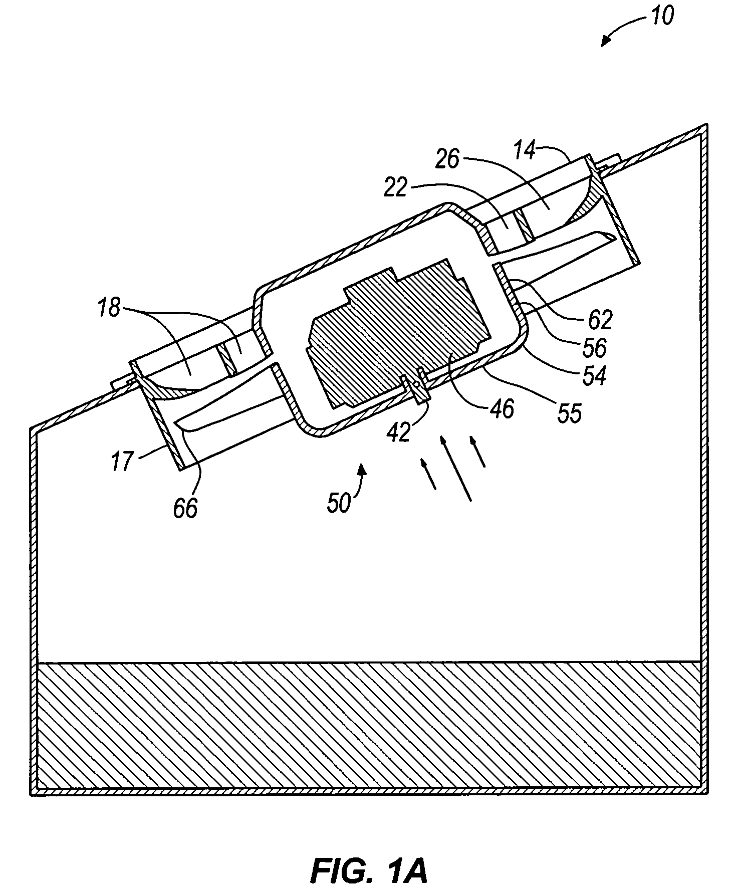
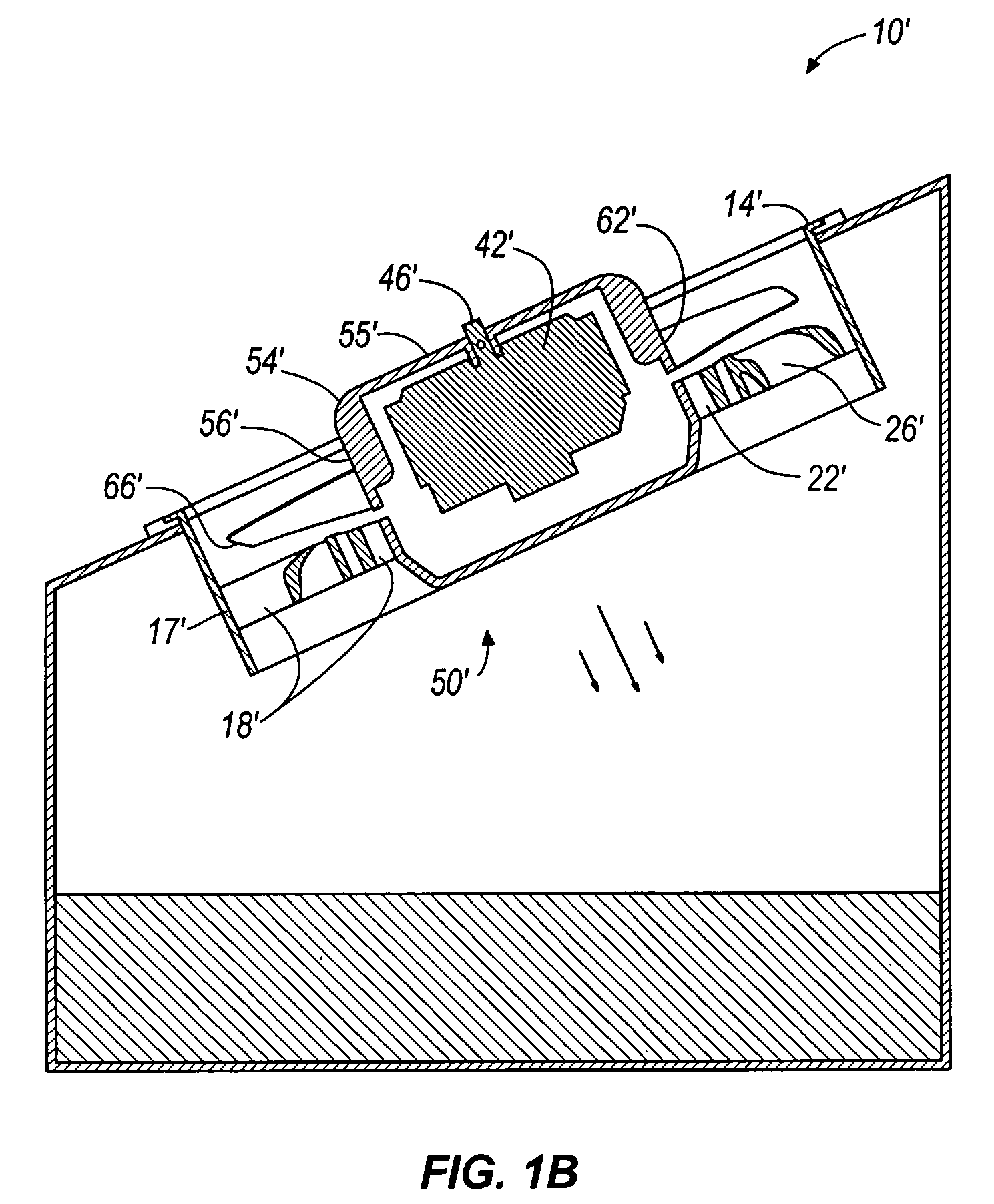
[0028] An exemplary embodiment of an axial flow fan assembly 10 according to the present invention is illustrated in FIGS. 1-10. The exemplary fan assembly 10 in FIGS. 1-10 has a shroud 14, a motor 42 coupled to the shroud 14, and a fan 50 coupled to the motor 42. In operation, the motor 42 rotates a drive shaft 46 coupled to the fan 50. As the drive shaft 46 rotates, it powers the fan 50 to rotate within the shroud 14, and generates air movement. FIGS. 1A and 1B illustrate the fan in an exemplary environment. As illustrated, the fan is mounted to generate a stream of air to remove heat from condensing coils. This is just one of the many possible uses of this fan. Although a heat exchange environment is described herein and illustrated in FIGS. 1A and 1B, the fan of the present invention can be employed in any air moving application. Other uses known by those having ordinary skill in the art fall within the spirit and scope of the present invention.

[0029] As illustrated in FIGS. 2-...


PUM


Abstract

The axial fan assembly according to some embodiments of the present invention has a shroud, a motor coupled to the shroud, and a fan coupled to the motor. By employing selected vane-to-blade ratios, blade twist angles, blade pitch angles, blade-to-shroud axial gaps, shroud solidities, vane swept angles, and vane inlet and outlet angles of specified amounts or falling within specified ranges, desirable fan performance is achieved. Any one or more of these parameters can be utilized alone or in combination with other parameters as desired.

Description

BACKGROUND OF THE INVENTION [0001] Fans are used to generate air movement in a wide variety of applications, such as in heating, ventilating, and cooling systems. For example, a variety of axial-type fans (i.e., fans in which fluid is moved in a direction along the axis of rotation of the fan) are used in many industrial applications such as for ventilation purposes in office buildings, greenhouses, barns, factories, and other structures. Axial ventilation fans also have residential uses, such as in kitchens and bathrooms. As previously mentioned, axial fans are also commonly used in heating and cooling systems for heat transfer purposes. For example, axial fans are used for heat transfer purposes in a variety of applications, such as in air conditioning units, refrigeration units, computers, and in cars and other vehicles. In most of these applications, the fan is used to move air across a heat exchanger, wherein heat is transferred to the air as it passes by and / or through the hea...

Claims


Application Information

Patent Timeline
25 Aug 2005
Publication
US20050186070A1
IPC
F04D29/54
CPC
F04D29/542; F04D29/544
Inventors
ZENG, LING-ZHONG; SHELBY, RICHARD R.