
Electrophysiology/ablation catheter having deflection assembly

a technology of electrostatic/ablation catheter and deflection assembly, which is applied in the field of electrostatic/ablation catheter with deflection assembly, can solve the problems of limiting the use or incorporation of additional components into the catheter assembly, affecting the accuracy of the catheter, and the available space within the catheter assembly including the catheter handle, etc., and achieves the effect of expanding the use and capabilities of the catheter assembly

Active Publication Date: 2005-08-25
ST JUDE MEDICAL ATRIAL FIBRILLATION DIV
View PDF9 Cites 56 Cited by
  • Summary
  • Abstract
  • Description
  • Claims
  • Application Information

AI Technical Summary

Benefits of technology

[0015] Another advantage of the invention resides in the independent actuation of the separate curvature sections.
[0016] Still another advantage of the invention resides in the ease with which the assembly may be actuated / operated.
[0017] Yet another advantage is found in the incorporation of the additional deflection assembly into a single catheter assembly, which expands the use and capabilities of the catheter assembly.
[0018] Still other benefits and advantages of the invention will become apparent to those skilled in the art upon reading and understanding the following detailed description.

Problems solved by technology

The additional bending feature, however, has been difficult to achieve because of the limited volume or available space within the catheter assembly.
This limitation also relates to the available space within the catheter assembly including the catheter handle as a result of the existence of electrical wires extending through the length of the catheter to communicate between the handle at the proximal end of the catheter and the electrodes disposed at the distal end.
Moreover, the deflection means or deflection assembly in other prior art arrangements has heretofore been of such size that it limits the use or incorporation of additional components into the catheter assembly.

Method used


Image

  • Electrophysiology/ablation catheter having deflection assembly
  • Electrophysiology/ablation catheter having deflection assembly
  • Electrophysiology/ablation catheter having deflection assembly

Examples


Embodiment Construction

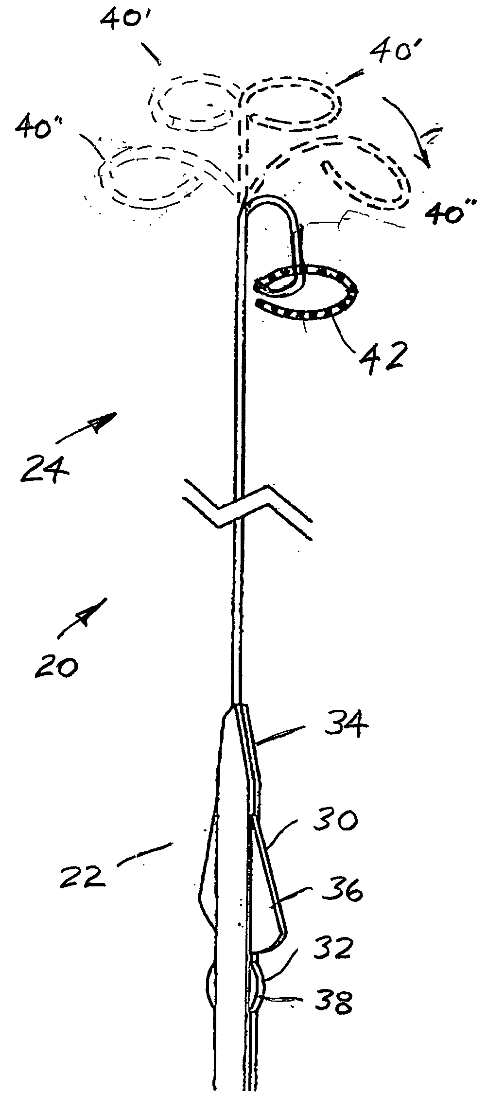
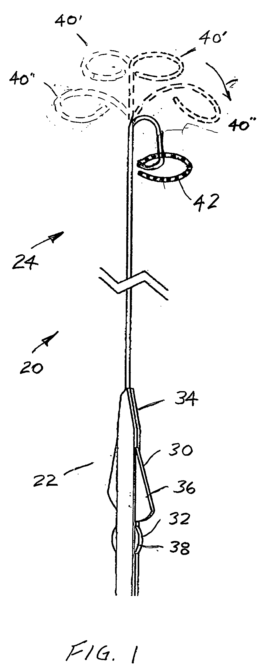
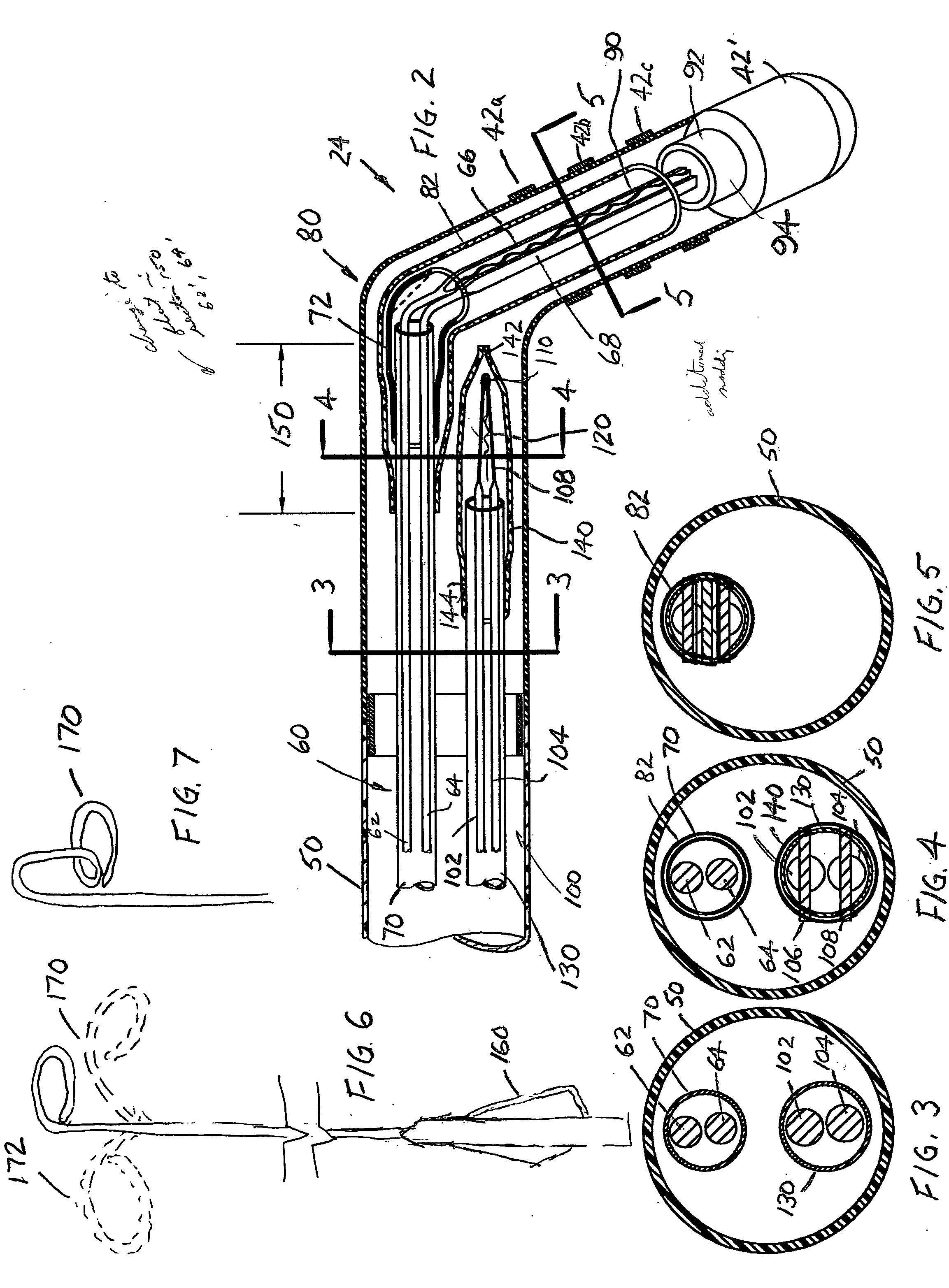
[0026] It will be appreciated that the structure, operation, and advantages offered by a catheter assembly that forms a first curvature or lariat configuration at a distal portion thereof is shown and described in the commonly owned U.S. published application. The structure and operation of the deflection assembly shown and described therein are helpful to an understanding of the present invention. A preferred embodiment of the present invention is shown in FIG. 1 and generally illustrates an electrophysiology / ablation catheter or catheter assembly 20. The catheter assembly includes a proximal portion 22 and a distal portion 24. Particularly, the proximal portion includes independent, axially spaced first and second actuators 30, 32. Each actuator is associated with a separate catheter deflection assembly to be described in greater detail below to achieve different, independent deflection or curvature of the distal portion of the catheter assembly. Moreover, each catheter deflection...


PUM


Abstract

An electrophysiology / ablation catheter assembly includes an elongated flexible casing that received a first catheter deflection assembly. Electrical leads are connected to each electrode on a distal portion of the catheter assembly and extend through the casing for external connection at a proximal end of the catheter assembly. A first actuator is operatively connected to the first catheter deflection assembly and operable upon movement to selectively effect displacement of the distal end. A second catheter deflection assembly is also disposed in the casing. A second actuator is connected adjacent the proximal end of the catheter deflection assembly and operable upon movement to selectively effect lateral displacement of the catheter at a location spaced from the first curved configuration of the distal end.

Description

BACKGROUND OF INVENTION [0001] This application is directed to a catheter assembly, and particularly an electrophysiology / ablation catheter of the type used for diagnostic and therapeutic medical procedures. It finds particular application in minimally invasive cardiac electrophysiology studies such as cardiac diagnostic or ablation procedures in which precise and controlled movement of conductive electrodes provided on a distal portion of the catheter are required. [0002] It is known from commonly owned U.S. Pat. Nos. 5,552,713 and 5,861,024 to provide an electrophysiology / ablation catheter to monitor and record intra-cardiac electrical signals. The details of these patents are expressly incorporated herein by reference. The electrical signals from the heart are conducted through the electrodes to associated monitoring and recording devices. The electrodes can also be used, for example, to deliver energy to the heart either as a stimulus to monitor the heart's response thereto or t...

Claims


Application Information

Patent Timeline
IPC IPC(8): A61B5/04A61B5/042A61B18/14
CPCA61B5/0422A61B5/6857A61B2018/00839A61B2018/00375A61B18/1492A61B5/287
Inventor RASHIDI, RASSOLL
Owner ST JUDE MEDICAL ATRIAL FIBRILLATION DIV
Learn More