
Robot with display device

a display device and robot technology, applied in computer control, program control, instruments, etc., can solve the problems of reducing efficiency, carrying the printed manual or the teaching pendant while working, etc., and achieve the effect of not complicating the wiring of the robot and achieving the power supply of the control uni

Inactive Publication Date: 2005-08-25
FANUC LTD
View PDF4 Cites 66 Cited by
  • Summary
  • Abstract
  • Description
  • Claims
  • Application Information

AI Technical Summary

Benefits of technology

[0005] The present invention provides a technology for eliminating inconvenience like that occurring when a person in charge of operation and maintenance of a robot has to check a printed manual or a display screen of a teaching pendant. Moreover, the present invention thereby prevents a reduction in efficiency with which such work as operation and maintenance is carried out.
[0010] According to the present invention, the display device having a flexible display screen is mounted on the robot, and therefore, when performing robot operation, maintenance, troubleshooting or the like, the flexible display screen can be attached on either a curved or a flat surface and used for displaying the required information. As a result, inconvenience like that occurring when having to check a printed manual or the screen of a teaching pendant (such as having no place to put the manual or teaching pendant, being unable to use one hand, and the like) can be eliminated.
[0011] In addition, providing the control unit of the display device with wireless communications means eliminates the need for wiring for transmitting and receiving control signals for display and signals expressing the display contents, and thus does not complicate the robot wiring. Power supply for the control unit can also be achieved simply, by use of a battery or by supplying power via the robot.

Problems solved by technology

However, at times a place to put the printed manual or the teaching pendant cannot be found, which is inconvenient.
In addition, having to carry the printed manual or the teaching pendant while working reduces efficiency.

Method used


Image

  • Robot with display device
  • Robot with display device
  • Robot with display device

Examples


Embodiment Construction

[0015] Preferred embodiments of the present invention are now described in detail referring to the accompanying drawings.

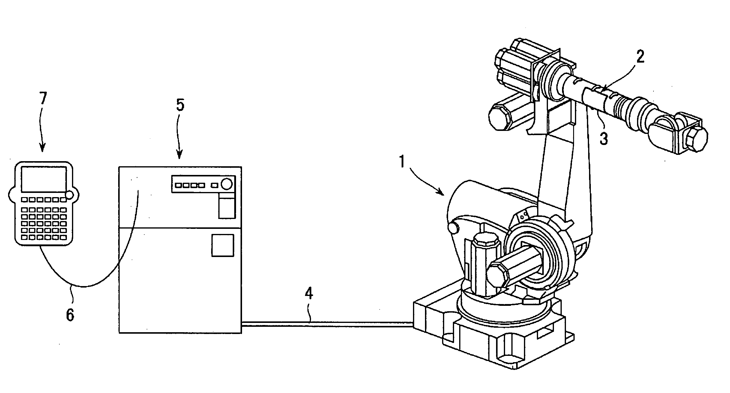
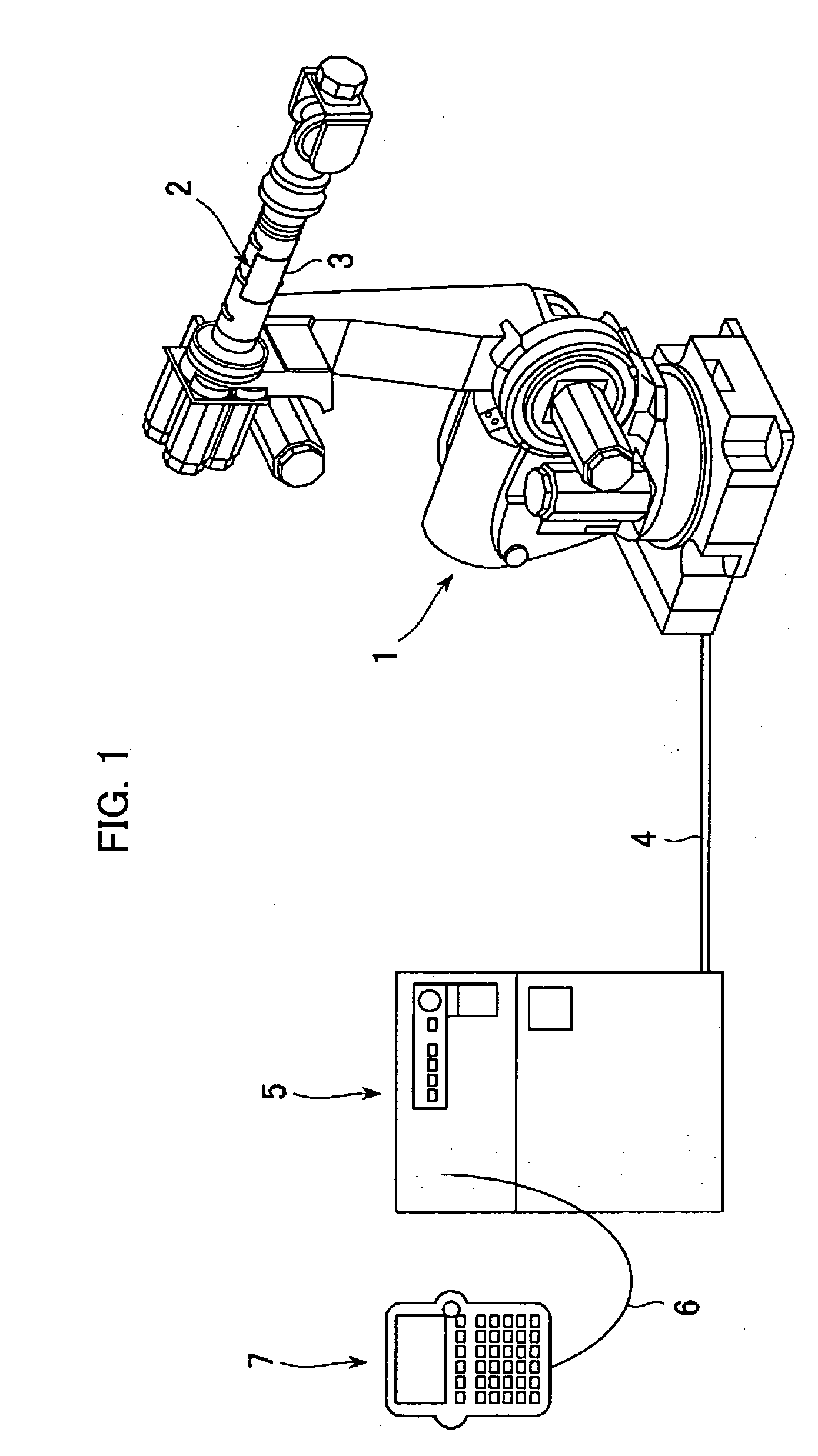
[0016]FIG. 1 is a diagram showing the general arrangement of a robot system according to one embodiment of the present invention. In FIG. 1, reference numeral 1 designates a robot (the overall mechanical portion), whose operations are controlled by a controller 5 connected to the robot by a cable 4. A teaching pendant 7 is connected to the robot controller 5 by a cable 6, so that, by operating the teaching pendant 7, the robot can be instructed and operated manually. This basic structure and function is not particularly different from the conventional robot system.

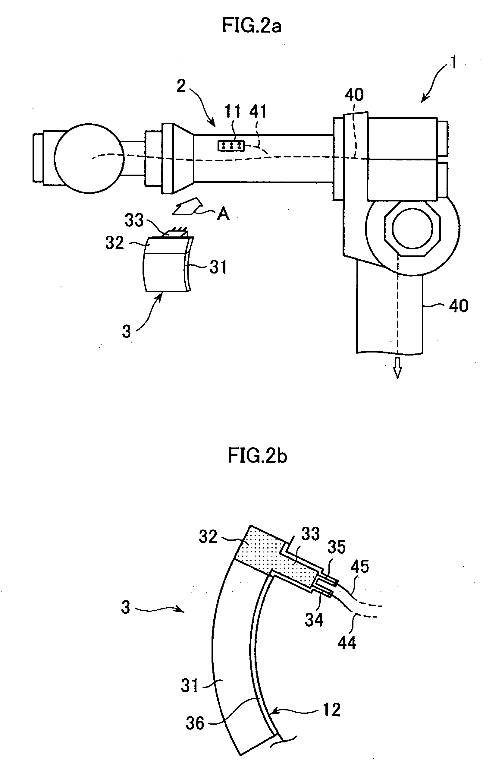
[0017] The present embodiment differs from the conventional art insofar as a mounting portion 2 is provided at a suitable location on the robot arm of the robot 1, at which a display device 3 is mounted. A device having a display screen using organic light-emitting diode (OLED) display elements is empl...


PUM


Abstract

A robot allowing an operator to refer to information required for inspections or the like without having to use a printed manual or a display screen of a teaching pendant. A display device has a flexible display screen that uses organic light-emitting diodes, a control unit, and a plug. The display device plug is inserted in a connector provided at a suitable location the robot arm, the display unit is lightly pressed onto the surface of the robot arm (the surface may be curved or flat) and a sticking part (an adhesive layer or magnetic layer) stuck onto and fixed to the surface. Instructions are transmitted from the teaching pendant to a robot controller. Electric power and signals are transmitted to the control unit through wiring and an image is displayed on the display unit. The technician carries on with the work of inspection while referring to the display screen. Alternatively, power may be supplied by battery and data exchanged by wireless communications. In addition, a holder that accepts and holds the display device may be provided on the robot arm.

Description

BACKGROUND OF THE INVENTION [0001] 1. Field of the Invention [0002] The present invention relates to a robot provided with a display device, and in particular to a technology for displaying information regarding operation and maintenance of the robot on a robot arm. [0003] 2. Description of Related Art [0004] Conventionally, a person responsible for the operation and maintenance of a robot on a factory production line or the like, in order to access information on how to operate or maintain the robot, has to either hold a printed manual or a teaching pendant and refer to the necessary information described on the printed manual or displayed on a screen of the teaching pendant. However, at times a place to put the printed manual or the teaching pendant cannot be found, which is inconvenient. In addition, having to carry the printed manual or the teaching pendant while working reduces efficiency. An effective technology for solving such a situation in a simple way has not yet been pro...

Claims


Application Information

Patent Timeline
Patent Type & Authority Applications(United States)
IPC IPC(8): B25J19/00
CPCB25J19/00
Inventor HASHIMOTO, YOSHIKICHINO, NOBUOHIRAMOTO, MASATOSHI
Owner FANUC LTD
Learn More