Turbocharger

a technology of turbocharger and turbine housing, which is applied in the direction of positive displacement liquid engine, piston pump, liquid fuel engine, etc., can solve the problems of unavoidable exhaust gas flow from the turbine housing through, and the emissive behavior is worsened

Inactive Publication Date: 2005-09-01
BORGWARNER INC
View PDF6 Cites 40 Cited by
  • Summary
  • Abstract
  • Description
  • Claims
  • Application Information

AI Technical Summary

Benefits of technology

[0004] It is an object of the present invention to reduce or to prevent the above-mentione

Problems solved by technology

This means that with an elevated exhaust gas pressure, i.e. with elevated numbers of revolution, the tendency can be observed that the exhaust gas flows from the turbine housing through unavoidable leakages into the region of the bearings, often accommodated in a separate bearing housing intermediate between the

Method used


Image

  • Turbocharger
  • Turbocharger

Examples


Embodiment Construction

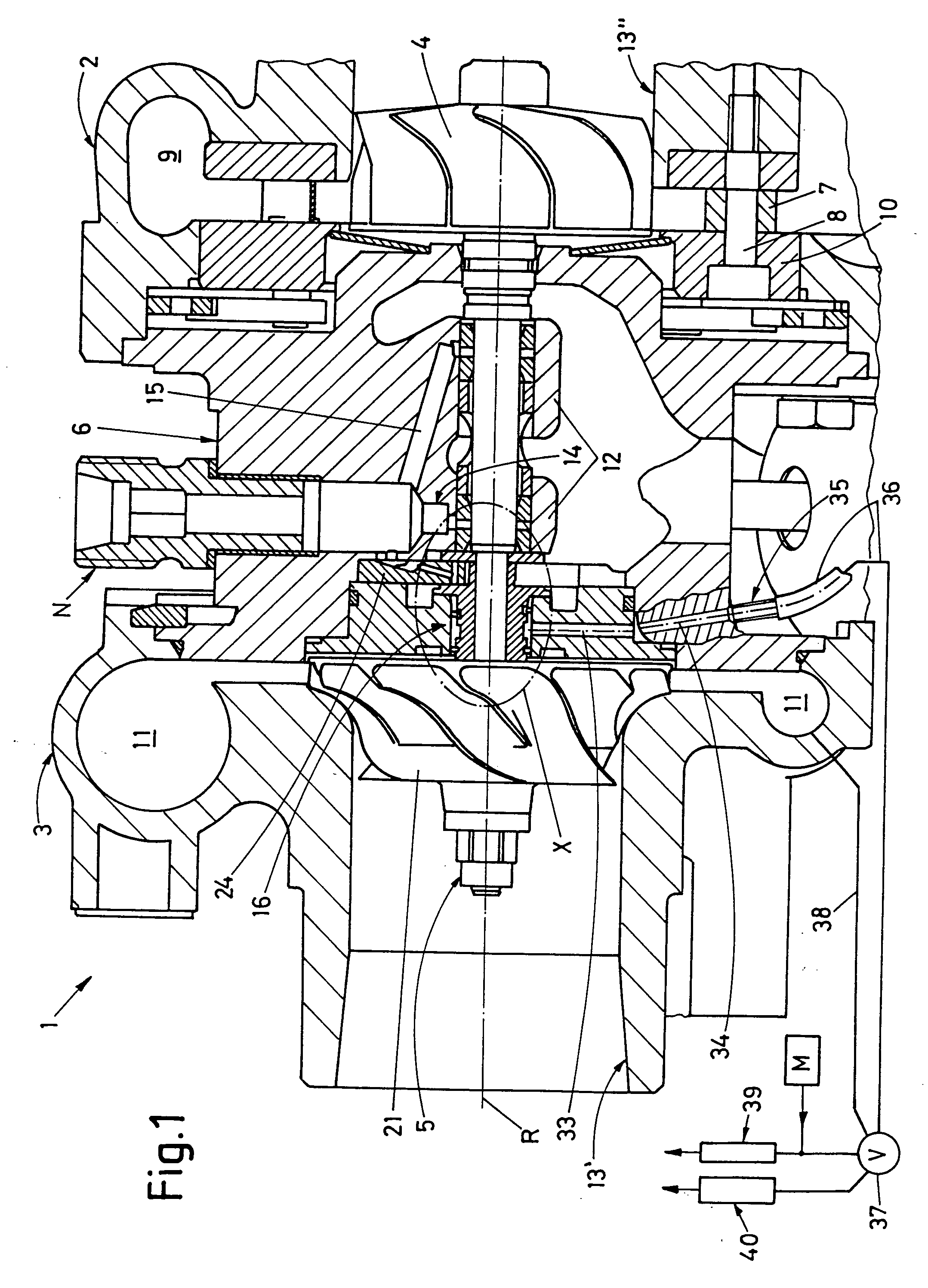
[0012] According to FIG. 1, a turbocharger 1 (only the center portion is represented, while portions at the left side and the right side are torn off) has in conventional manner a turbine housing part 2 and a compressor housing part 3 connected to the turbine housing 2, both being arranged along an axis of rotation R. The turbine housing part 2 is in cross-section and shows a turbine rotor 4 situated on and rotatable about the axis of rotation R. The turbine rotor 4 is fastened to one end of a rotor shaft 5 supported in a housing center part 6.

[0013] It should be noted that the term “end” of the rotor shaft should mean that portion of the shaft which projects into the respective turbine housing (one end) or compressor housing (other end). However, it is also known to prolong the shaft, for example, into a second turbine housing opposite the first turbine housing which embodiment should also be in the scope of the present invention. Moreover, the above-mentioned center part 6 may co...


PUM


Abstract

Turbocharger comprising a rotor shaft (5), a turbine housing (2), a compressor housing (3) connected to the turbine housing (2), and including at least one air supply channel (13′) for supplying air to be compressed and at least one discharge channel (11) for delivering compressed air. One end of the rotor shaft projects into the compressor housing and supports a compressor rotor (21). A bearing (12) in the region of the compressor rotor supports the rotor shaft, and forms a bearing gap. The bearing includes two seals (29,30) axially spaced from one another to seal the bearing gap and to leave an intermediate space (31) between them. A suction channel (33,34) is connected to a vacuum source and sucks gas out of this intermediate space.

Description

FIELD OF THE INVENTION [0001] The present invention relates to a turbocharger comprising a rotor shaft that defines an axis of rotation. One end of the rotor shaft projects into a turbine housing having at least one supply channel for en exhaust gas, wherein at least one turbine rotor is fastened to the rotor shaft and is, thus, rotatably supported. The exhaust gas from the supply channel is fed to the periphery of the turbine rotor. Moreover, there is a compressor housing which comprises at least one air supply channel. Into this compressor housing projects the other end of the rotor shaft. To this end of the rotor shaft, at least one compressor rotor is secured from whose periphery compressed air is discharged into an air discharge channel. A bearing arrangement is provided at least in the region of the compressor rotor, and this bearing arrangement comprises a sealing arrangement. BACKGROUND OF THE INVENTION [0002] In turbochargers of this kind, a phenomenon is occurring during o...

Claims


Application Information

Patent Timeline
IPC IPC(8): F01D25/18F02B39/00F16J15/00
CPCF01D25/183F05D2260/6022F05D2220/40F16J15/004
Inventor FRANKENSTEIN, DIRK
Owner BORGWARNER INC
Why Eureka
Try Eureka