
Fuel injection pump

a fuel injection pump and pump body technology, applied in the direction of pump, positive displacement liquid engine, machine/engine, etc., can solve the problems of high fuel injection load, frictional heat seized on the sliding contact portion,

Inactive Publication Date: 2005-09-01
DENSO CORP
View PDF7 Cites 9 Cited by
  • Summary
  • Abstract
  • Description
  • Claims
  • Application Information

AI Technical Summary

Benefits of technology

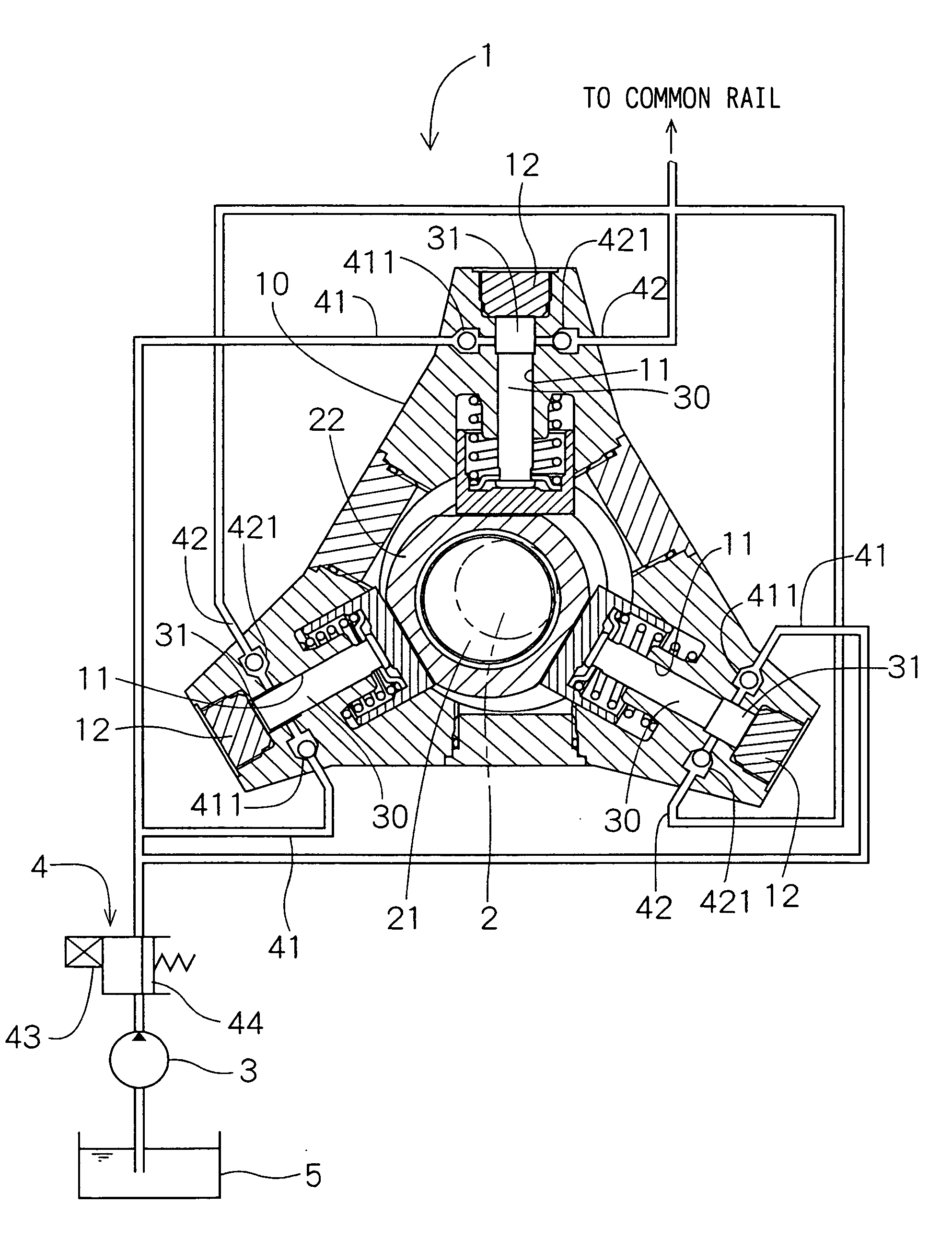
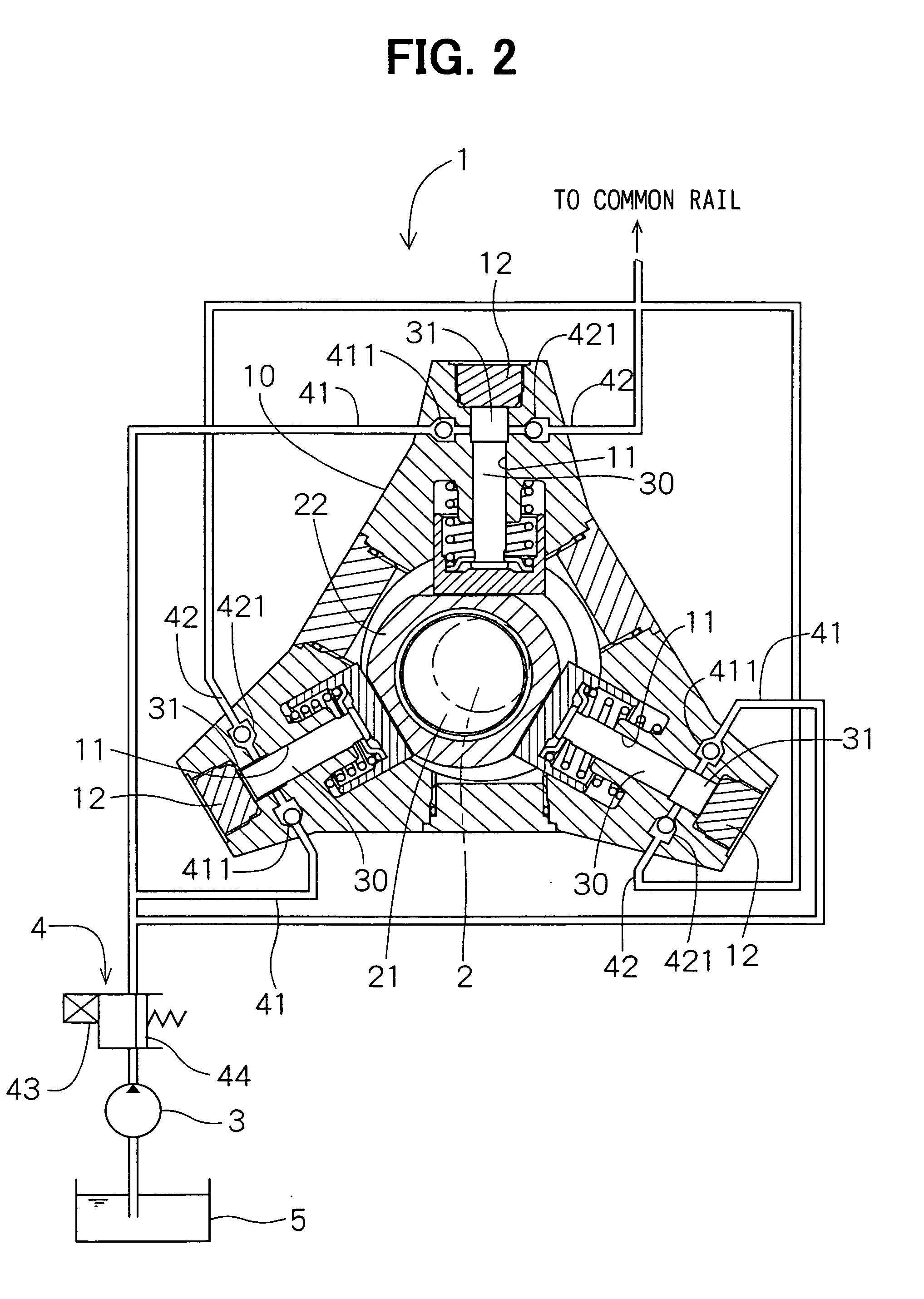
[0011] An object of the present invention is to provide a fuel injection pump whose construction is simpler and enables to deliver high pressure fuel and whose slidable contact portions are hardly seized with frictional heat.
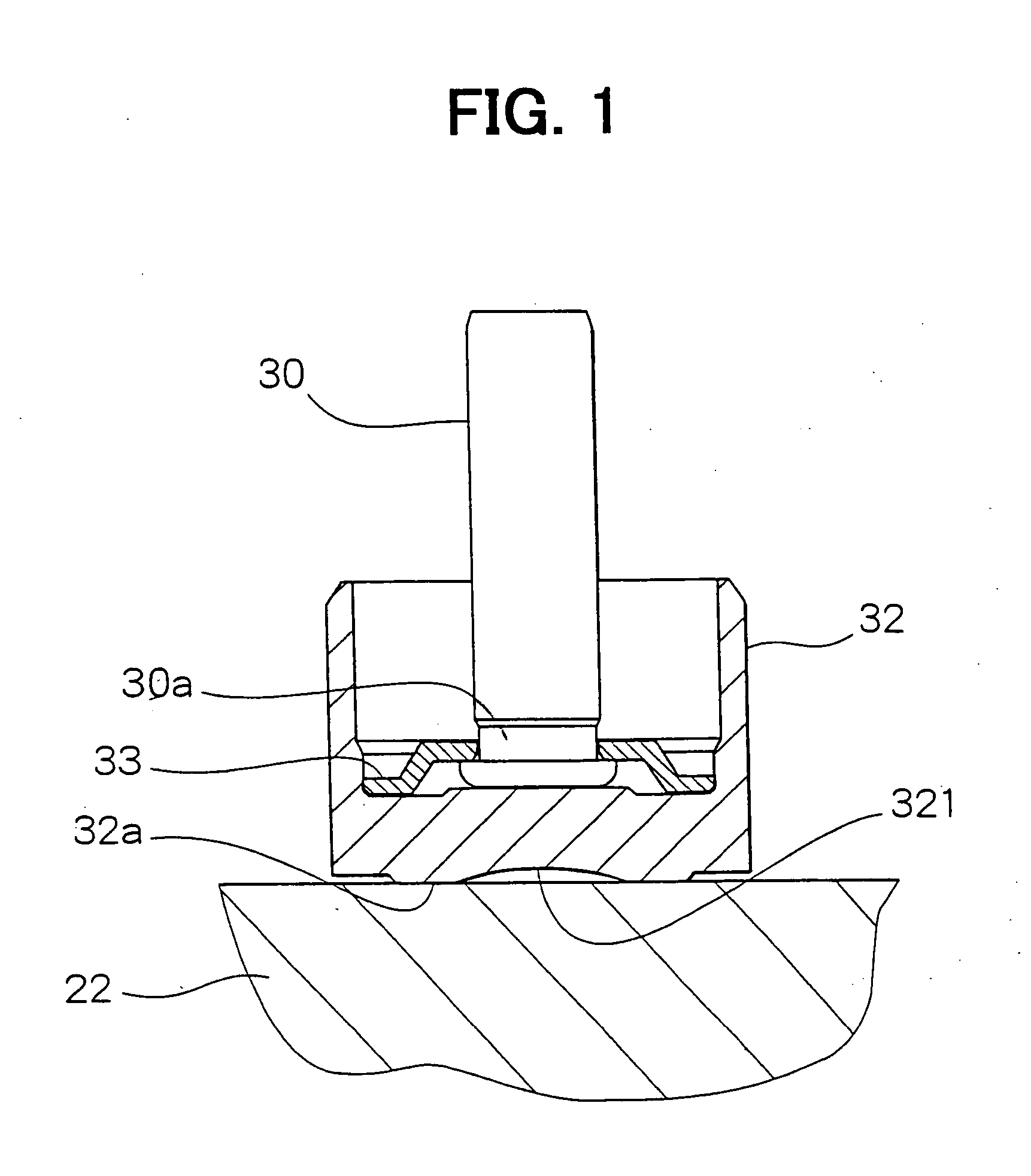
[0014] Accordingly, contact pressure between the plunger and cam ring members and contact pressure between the cam ring member and the eccentric cam are higher at a position away from the axial center line of the plunger member, when the transmitting force is low, but, as the transmitting force becomes stronger, is equalized between the positions away from and closer to the axial center line of the plunger member since the diameter of the hollow becomes smaller due to resilient deformation of the plunger or cam ring member. Since high pressure does not concentrate on the axial center line of the plunger member, the hollow serves to prevent the sliding contact portions between the plunger and cam ring members from being seized with frictional heat.

Problems solved by technology

However, to secure the higher injection pressure of the fuel, it is necessary to increase a force with which the fuel injection pump compresses the fuel so that the load of the fuel injection is very high.
In particular, when higher force is applied to contact portions of the fuel injection pump in slidable contact with each other, the contact portions tend to be seized with frictional heat.
As a result, large face pressure is produced on a slidable contact portion between the protruding portion of the drive force transmission member due to the resilient deformation thereof and the cam ring so that the slidable contact portion tends to be seized with frictional heat.

Method used


Image

  • Fuel injection pump
  • Fuel injection pump
  • Fuel injection pump

Examples


second embodiment

[0051] A fuel injection pump according to a second embodiment is described with reference to FIG. 7. Arrow marks shown in FIG. 7 illustrate schematically direction and magnitude of forces acting on the plunger and the cam ring.

[0052] The fuel injection pump 1 according to the second embodiment differs from that of the first embodiment in such a point that a tappet 50 is provided on a side of the cam ring with a shoe 60 as the drive force transmission member.

[0053] As shown in FIG. 7, the tappet 50, whose cross section is formed in a letter H shape, is cylindrical and has two inside spaces 52 and 53 that are divided by a partition 51. The plunger 30 is accommodated in the inside space 52 on a side opposite to the cam ring 22 so as to be in contact with the partition 51. The shoe 60 is press fitted to the inside space 53 on a side of the cam ring 22. The shoe 60 is formed in a column shape and made of high hardness material. The shoe 60 is provided with a sliding face 60a that is in...

third embodiment

[0056] A fuel injection pump according to a third embodiment is described with reference to FIG. 8. Arrow marks shown in FIG. 8 illustrate schematically direction and magnitude of forces acting on the plunger and the cam ring.

[0057] The fuel injection pump 1 according to the third embodiment differs from that of the first embodiment in such a point that a plunger 70 and a plunger head 71 as the drive force transmission member are formed into an integrated body, that is, integrally formed with same material. The plunger head 71 is in slidable contact with the cam ring 22.

[0058] The plunger head 71 is provided at an end thereof on a side of the cam ring 22 with a hollow 711. Depth and diameter of the hollow 711 are same as those of the first embodiment. Similarly to the first embodiment, the force applied to the plunger 70 is dispersed to the surrounding outside the hollow 711 in the plunger head 71, resulting in less local frictional heat seizure.

[0059] According to the third embo...

fourth embodiment

[0060] A fuel injection pump according to a fourth embodiment is described with reference to FIGS. 9A and 9B.

[0061] According to the fourth embodiment, a cam ring 80 is provided on an inner circumferential face thereof with a hollow 81. The hollow 81 is formed in shape of a ring groove along the inner circumferential face of the cam ring 80, as shown in FIG. 9B. Depth of the hollow 81 as viewed in a cross section of the cam ring 80 taken along an axial line thereof is deeper from an outer periphery thereof toward a center thereof and the center of the hollow 81 is positioned on an axial line of a plunger 82, as shown in FIG. 9A. The plunger 82 and a tappet 83 constituting the drive force transmission member are integrally formed. As an alternative, the plunger 82 may be formed separately from the tappet 83, similarly to the first embodiment. The plunger 82 and the tappet 83, whether or not they are integrated or separated, constitute a plunger member.

[0062] A bush 23 is inserted b...


PUM


Abstract

In a fuel injection pump, a tappet is provided on an end thereof on a side of a cam ring with a hollow. Force acting on the tappet from a plunger due to fuel pressure is dispersed to a sliding contact surface outside the hollow so that contact face pressure between the tappet and the cam ring is smaller. As the fuel pressure becomes higher, larger resilient deformation of the tappet causes a diameter of the hollow smaller so that the tappet comes in flat slidable contact with the cam ring, resulting in preventing the contact portion between the tappet and the cam ring from being seized with frictional heat.

Description

CROSS REFERENCE TO RELATED APPLICATIONS [0001] This application is a division of U.S. application Ser. No. 10 / 173,800 filed Jun. 19, 2002, the entire contents of which are incorporated herein. This application is based upon and claims the benefit of priority of Japanese Patent Applications No. 2001-184957 filed on Jun. 19, 2001 and No. 2002-5026 filed on Jan. 11, 2002, the contents of which are incorporated herein by reference.BACKGROUND OF THE INVENTION [0002] 1. Field of the Invention [0003] The present invention relates to a fuel injection pump for internal combustion engines (hereinafter called engines), in particular, a high pressure pump having a plunger to be reciprocatingly driven by an eccentric cam. [0004] 2. Description of Related Art [0005] In a conventional high pressure pump, a plunger is axially and reciprocatingly driven via a cam ring by a cam for transmitting a driving force. The cam is eccentrically mounted on a drive shaft and the cam ring revolves round the driv...

Claims


Application Information

Patent Timeline
Patent Type & Authority Applications(United States)
IPC IPC(8): F02M59/06F02M59/10F02M59/44F02M63/02F04B9/04
CPCF02M59/06F02M63/0225F02M59/44F02M59/102
Inventor FURUTA, KATSUNORI
Owner DENSO CORP
Learn More