Rare earth permanent magnet

a permanent magnet, rare earth technology, applied in the direction of magnetic bodies, electric furnaces, furnaces, etc., can solve the problems of difficult to maintain effective coercive force, difficult to apply to practical magnets used at room temperature and above, and different concentration fluctuations that cannot be found even at the atomic level. , to achieve the effect of simple process

Active Publication Date: 2005-09-01
SHIN ETSU CHEM IND CO LTD
View PDF14 Cites 6 Cited by
  • Summary
  • Abstract
  • Description
  • Claims
  • Application Information

AI Technical Summary

Benefits of technology

[0024] As described in detail below, the present invention provides a permanent magnet which is observed as a uniform structure without microstructures, but shows a pinning-type initial magnetization curve. A two-phase separated structure as described above in the background is formed by a complex heat treatment, and thus it is not possible to form the magnet simply by sintering. On the other hand, according to the present invention, a permanent magnet which i

Problems solved by technology

However, although with this analytical method the concentration distribution of Co and Cu was investigated in detail, distinct concentration fluctuations could not be found even at an atomic level.
From these observed results, it is considered that it is difficult to maintain effective coercive force based on conventional intrinsic pinning at room temperature, and that such a coercivity mechanism is a phenomenon observed only at low temperatures at which a thin domain wall width can be realiz

Method used


Image

  • Rare earth permanent magnet
  • Rare earth permanent magnet
  • Rare earth permanent magnet

Examples


example 1

[0095] An alloy was fabricated by weighing out 99.9% pure Sm, Co, Fe and Ti or V corresponding to Sm(FeresCo0.20Ti0.065)8.3 or Sm(FeresCo0.20V0.09)8.3; melting them in a high frequency furnace in a reduced pressure argon atmosphere; and casting in a water cooled mold. The alloy was micro ground to an average particle diameter of 4 μm in a jet mill using N2 gas. While aligning the magnetic field of the micro powder in a magnetic field of 15 kOe, the particles were pressure molded at a pressure of 1 ton / cm2 to provide a molded body. In an argon gas atmosphere, the molded body was sintered at 1210° C. for one hour, and sequentially followed by solution heat treatment at 1195° C. for two hours to fabricate a sintered body. Subsequently, the sintered body was cut into thin sintered plates having a thickness of 0.5 mm by cutting. The thin plates, and the alloy micro powder (powder of approximately 4 μm), were both maintained at a temperature of 500° C., with introduced N2 gas and then nit...

example 2

[0098] An alloy was fabricated by weighing out 99.9% pure Sm, Co, Fe, Cu and Zr corresponding to Sm(CoresFe0.20Cu0.15Zr0.025)7.5; melting them in a high frequency furnace in a reduced pressure argon atmosphere; and casting in a water cooled mold. The alloy was micro ground to an average particle diameter of 4 μm in a jet mill using N2 gas. While aligning the magnetic field of the micro particles in a magnetic field of 15 kOe, the particles were pressure molded at a pressure of 1 ton / cm2 to provide a molded body. In an argon gas atmosphere, the molded body was sintered at 1210° C. for one hour, and sequentially followed by, solution heat treatment at 1195° C. for two hours to fabricate a sintered body. Aging heat treatment, typically performed on the 2-17 SmCo-based magnet, was not performed at all.

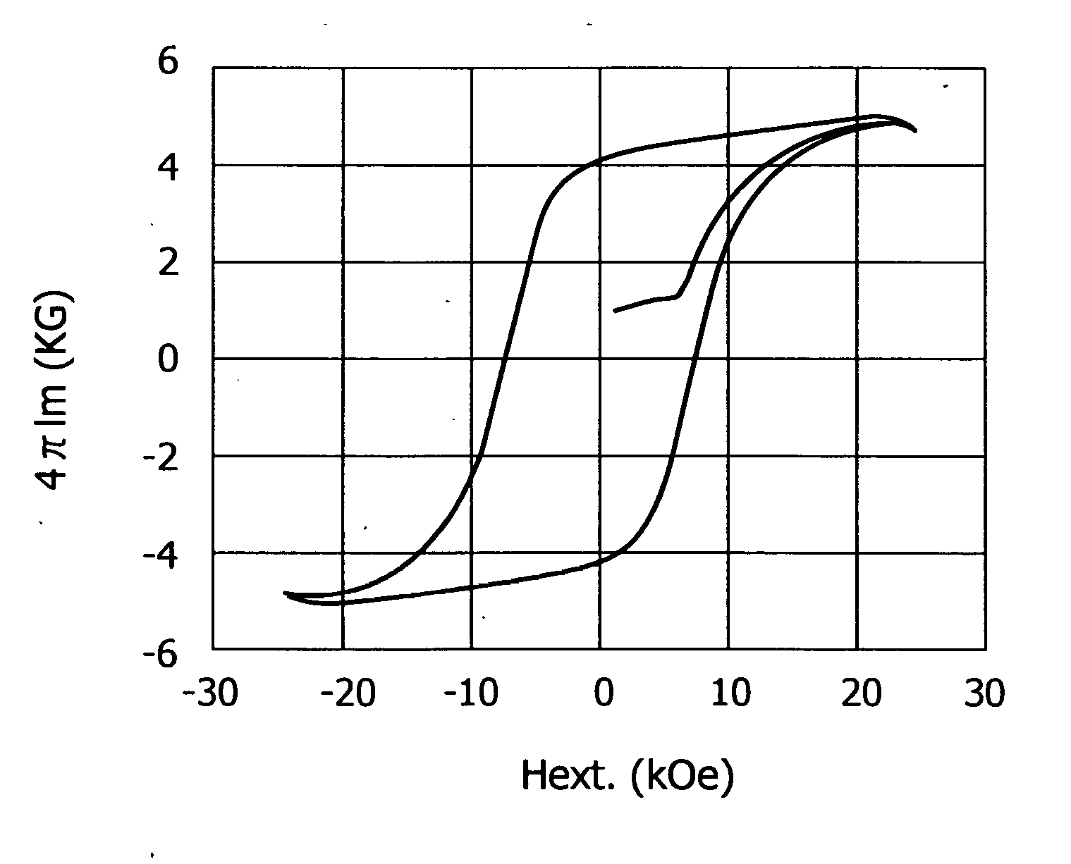
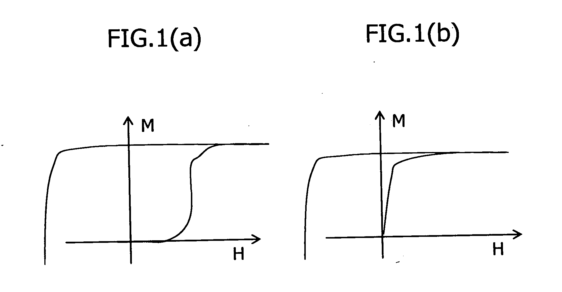
[0099] The hysteresis curve of the sintered body was measured by a BH tracer, and it showed a pinning-type initial magnetization curve, as shown in FIG. 7. It had a coercive force of Hci=...


PUM

PropertyMeasurementUnit
Lengthaaaaaaaaaa
Pressureaaaaaaaaaa
Nanoscale particle sizeaaaaaaaaaa

Abstract

It is an object of the present invention to provide a permanent magnet which is observed as a uniform structure without microstructures, but shows a pinning type initial magnetization curve. There is provided a rare earth permanent magnet comprising a magnetic intermetallic compound comprising R, T, N and an unavoidable impurity, wherein R is one or more rare earth elements comprising Y, T is two or more transition metal elements and comprises principally Fe and Co; wherein the magnetic intermetallic compound has an T/R atomic ratio of 6 to 14; a magnetocrystalline anisotropy energy of at least 1 MJ/m3; a Curie point of at least 100° C.; average particle diameter of at least 3 μm; and a substantially uniform structure; wherein the rare earth permanent magnet has a structure that gives a pinning-type initial magnetization curve; and wherein the magnetic intermetallic compound has a Th2Zn17-type structure, and the like.

Description

BACKGROUND OF THE INVENTION [0001] 1. Field of the Inention [0002] The present invention relates to rare earth permanent magnets, and particularly relates to rare earth permanent magnets having a uniform structure. The rare earth permanent magnets according to the present invention are suitable for use in devices such as electronic apparatuses, motors and actuators for electrical devices, and synchronous motors which requires heat-resistance, position sensors for electrical devices and rotation sensors and the like. [0003] 2. Description of Related Art [0004] 2-17-type Sm—Co-based magnets, whose typical structure is, for example, Sm(CoFeCuT)7.5, wherein T is Zr, Ti or the like, have high magnetic characteristics, excellent temperature characteristics, and corrosion-resistance, and are widely utilized as well as NdFeB-based magnets. [0005] 2-17-type Sm—Co-based magnets show a magnetic domain wall pinning type coercivity mechanism (FIG. 1a), and is different from 1-5 type Sm—Co-based ...

Claims


Application Information

Patent Timeline
IPC IPC(8): C22C1/04C22C38/00H01F1/053H01F1/055H01F1/059
CPCB22F2998/00B22F2999/00C22C1/0441C22C38/005H01F1/0536H01F1/0557H01F1/0596B22F9/04B22F3/02B22F3/10B22F2202/05
Inventor OHASHI, KEN
Owner SHIN ETSU CHEM IND CO LTD
Why Eureka
Try Eureka