Switching power-supply module

a power supply module and power supply technology, applied in the direction of electric variable regulation, process and machine control, instruments, etc., can solve the problem of increasing the heat dissipation of components, and achieve the effect of improving the freedom of circuit design and reducing the number of switching power supply circuits

Active Publication Date: 2005-09-01
MURATA MFG CO LTD
View PDF10 Cites 45 Cited by
  • Summary
  • Abstract
  • Description
  • Claims
  • Application Information

AI Technical Summary

Benefits of technology

[0014] To overcome the problems described above, preferred embodiments of the present invention provide a switching power-supply module that easily improves the freedom of circuit design, and a switching power-supply module that reduces the number of switching power-supply circuits that are wastefully discarded.

Problems solved by technology

This arrangement greatly increases heat dissipation of components.

Method used


Image

  • Switching power-supply module
  • Switching power-supply module
  • Switching power-supply module

Examples


Embodiment Construction

[0035] Preferred embodiments of the present invention will be described below with reference to the accompanying drawings.

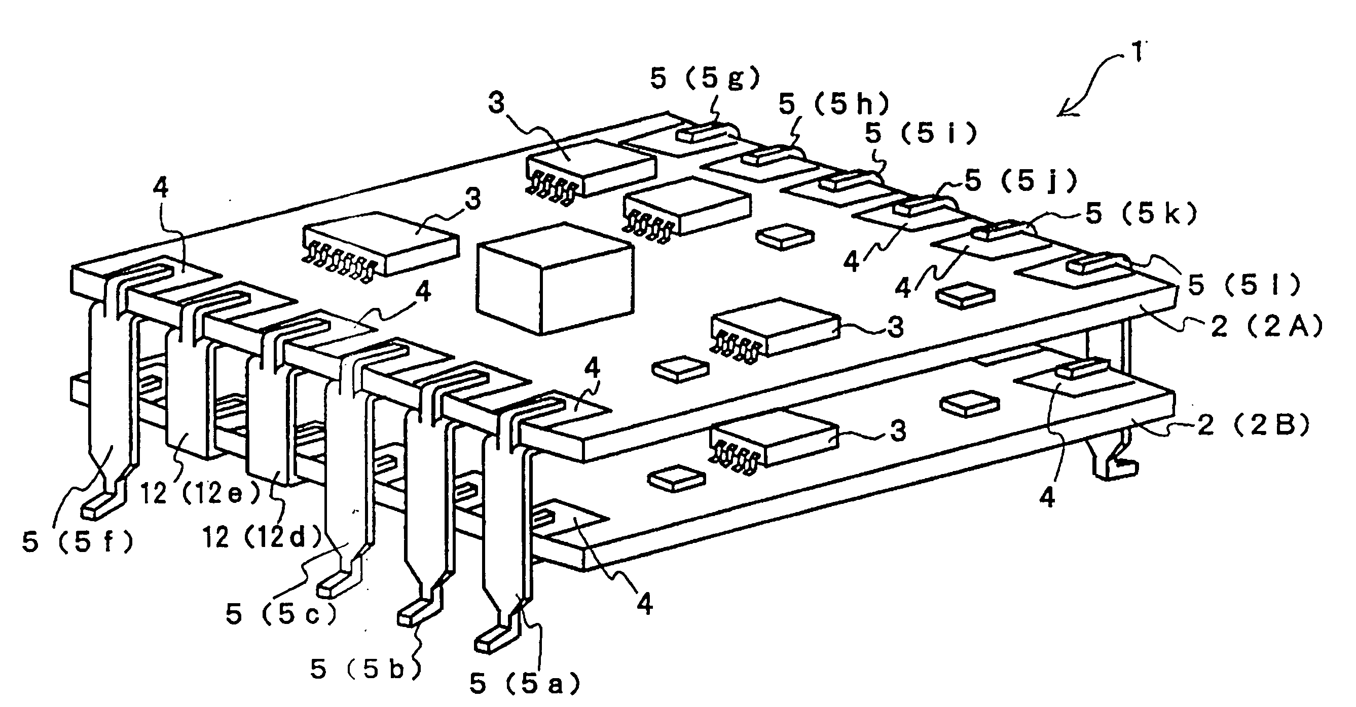
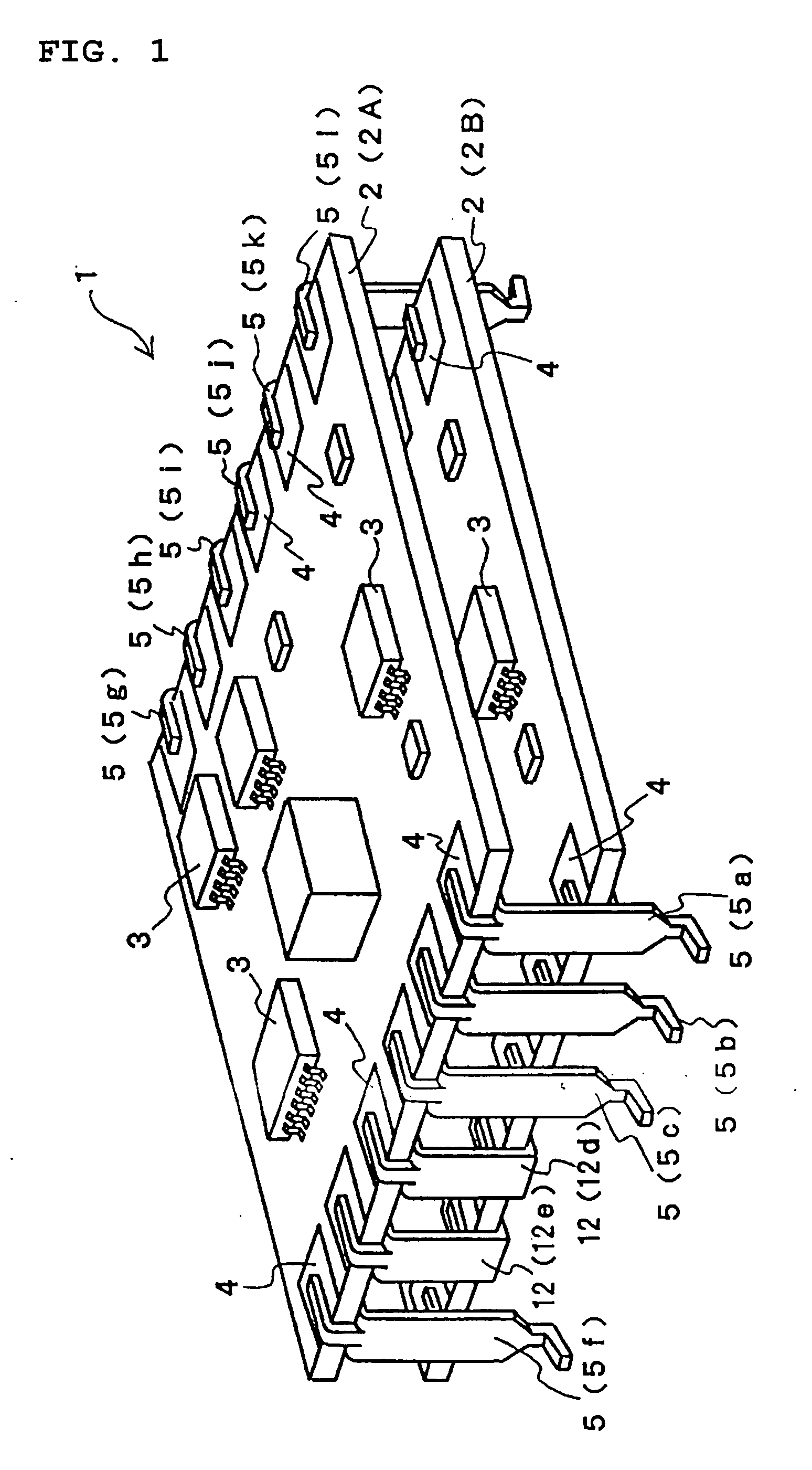
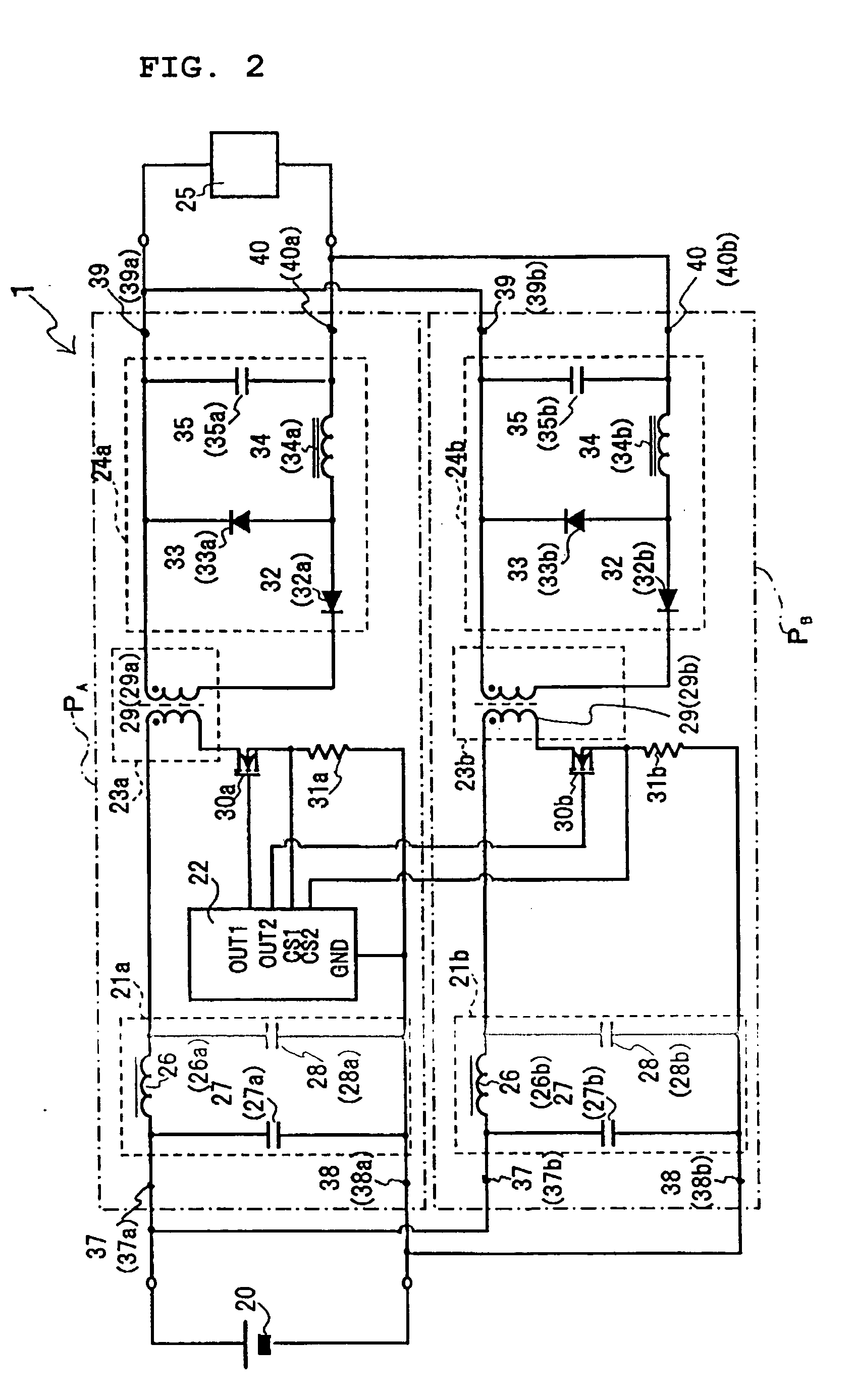
[0036]FIG. 1 is a schematic perspective view of a switching power-supply module according to a first preferred embodiment of the present invention. FIG. 2 is a schematic circuit diagram of the switching power-supply module of the first preferred embodiment. FIG. 3 shows exemplary waveforms of operations of major circuit sections of the switching power-supply module of the first preferred embodiment. In the following description of the first preferred embodiment, the same elements and portions as those in the switching power-supply module shown in FIGS. 8A and 8B are denoted with the same reference numerals and the descriptions thereof are omitted.

[0037] A switching power-supply module 1 of a first preferred embodiment includes a plurality of circuit boards 2 (2A and 2B). Along opposing edges of the circuit boards 2 (2A and 2B), a plurality of conductor land pat...


PUM


Abstract

A switching power-supply module includes circuit boards, power conversion circuit sections provided on the respective circuit boards, conductor land patterns provided with spacing therebetween along edges of the circuit boards, conductor terminals for interconnecting the conductor land patterns. The circuit boards are stacked with spacing therebetween with the corresponding conductor land patterns being aligned, and the aligned conductor land patterns are interconnected by the corresponding conductor terminals. At least one of the conductor terminals includes an interboard-connection portion for interconnecting the conductor land patterns of the circuit boards and a leg portion that extends from the interboard-connection portion in the stacking direction of the circuit boards and that defines an external-connection portion, and the other conductor terminals each function as an interboard-connection dedicated terminal for providing connection between the circuit boards.

Description

BACKGROUND OF THE INVENTION [0001] 1. Field of the Invention [0002] The present invention relates to a switching power-supply module in which switching power-supply circuits, such as inverters or DC-DC converters, are provided on circuit boards. [0003] 2. Description of the Related Art [0004]FIG. 8A is a schematic perspective view of one example of a switching power-supply module (e.g., Japanese Unexamined Patent Application Publication No. 2002-58247). In FIG. 8A, reference numeral 1 indicates a switching power-supply module and reference numeral 2 (2A and 2B) indicates circuit boards. Reference numeral 3 indicates electronic components mounted on the circuit boards 2 (2A and 2B). The electronic components 3 and wiring patterns (not shown) define switching power-supply circuits on the circuit boards 2 (2A and 2B). [0005] Reference numeral 4 indicates conductor land patterns, which are provided at edges of the circuit boards 2 (2A and 2B). Reference numeral 5 indicates conductor ter...

Claims


Application Information

Patent Timeline
Patent Type & Authority Applications(United States)
IPC IPC(8): H02M3/28H01L31/109H02M3/335H02M7/00H05K1/14H05K3/34H05K3/36
CPCH02M3/33538H02M7/003H02M2001/0074H05K2201/10386H05K3/3405H05K3/3421H05K3/368H05K1/144H02M1/0074
Inventor MATSUMOTO, TADAHIKOHONDA, SYUICHIOHASHI, YASUOSANO, NAOTO
Owner MURATA MFG CO LTD
Why Eureka
Try Eureka