Electronic component products and method of manufacturing electronic component products

a technology of electronic components and products, applied in the field of three-dimensional inspection apparatus, a manufacturing method of electronic components, can solve the problems of erroneous data, long inspection time, erroneous data, etc., and achieve the effect of reducing the angle of view and inspection, and increasing the apparent spacing

Inactive Publication Date: 2005-09-01
SCANNER TECH CORP
View PDF90 Cites 8 Cited by
  • Summary
  • Abstract
  • Description
  • Claims
  • Application Information

AI Technical Summary

Benefits of technology

[0011] The system optics are designed to focus images for all perspectives without the need for an additional focusing element. The optics of the side views may incorporate a nonlinear element to stretch the image in one direction to increase the apparent spacing between adjacent ball images allowing a lower angle of view and inspection of BGA's with closely spaced balls.

Problems solved by technology

This method requires a large number of measurement samples to determine the dimensions of the BGA resulting in longer inspection times. This method also suffers from specular reflections from the smooth surfaces of the solder balls resulting in erroneous data.
This method suffers from the problem of low contrast contour lines resulting in missed counting of the number of contours and resulting in erroneous data.
This method also suffers from the contour lines merging at surfaces with steep slopes, such as the sides of the balls on the BGA, resulting in an incorrect count of the number of contours and resulting in erroneous data.
This method suffers from specular reflections due to the highly focused nature of the light bands resulting in erroneous data.
This method further suffers from increased inspection times due to the number of images required.
This method suffers from the need for a higher angle of view of the ball from the second camera resulting in looking at a point significantly below the top of the ball for BGA's having fine pitch.
This method also suffers from limited depth of focus for the second camera limiting the size of BGA's that can be inspected.
This system can only inspect BGA's and not other device types such as gullwing and J lead devices.
The prior art does not provide two separate and opposite side views permitting larger BGA's to be inspected or nonlinear optics to enhance the separation between adjacent ball images in the side perspective view.

Method used


Image

  • Electronic component products and method of manufacturing electronic component products
  • Electronic component products and method of manufacturing electronic component products
  • Electronic component products and method of manufacturing electronic component products

Examples


Embodiment Construction

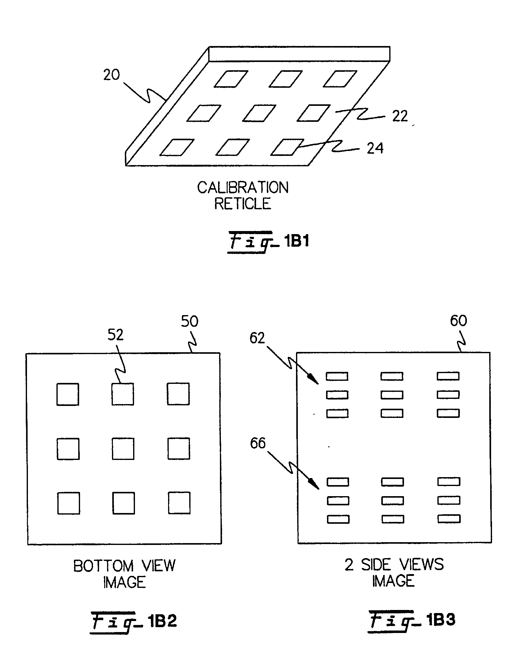
[0044] In one embodiment of the invention, the method and apparatus disclosed herein is a method and apparatus for calibrating the system by placing a pattern of calibration dots of known spacing and size on the bottom plane of a calibration reticle. From the precision dots the missing state values of the system are determined allowing for three dimensional inspection of balls on ball grid array devices, BGA devices or balls on wafers or balls on die. In one embodiment of the invention the system may also inspect gullwing and J lead devices as well as ball grid arrays.

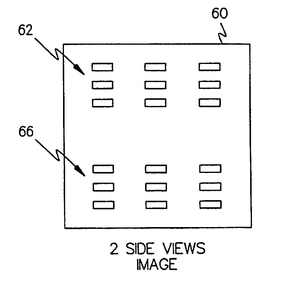
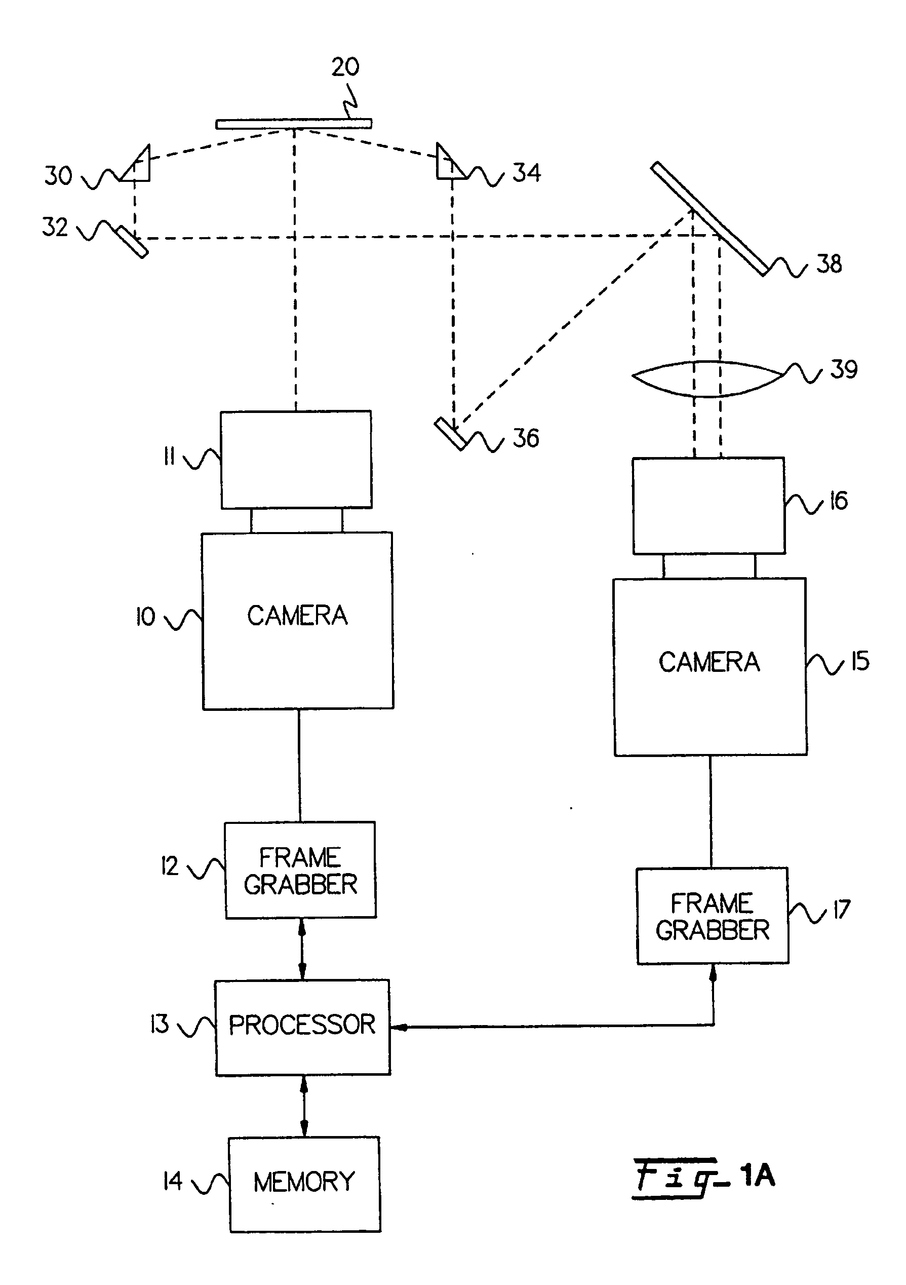
[0045] Refer now to FIG. 1A which shows the apparatus of the invention configured with a calibration reticle for use during calibration of the state values of the system. The apparatus obtains what is known as a bottom image 50 of the calibration reticle 20. To take the bottom image 50 the apparatus includes a camera 10 with a lens 11 and calibration reticle 20 with a calibration pattern 22 on the bottom surface. The ...


PUM

PropertyMeasurementUnit
shapeaaaaaaaaaa
angle of viewaaaaaaaaaa
anglesaaaaaaaaaa

Abstract

A calibration and part inspection method for the inspection of ball grid array, BGA, devices. Two cameras image a precision pattern mask with dot patterns deposited on a transparent reticle. The precision pattern mask is used for calibration of the system. A light source and overhead light reflective diffuser provide illumination. A first camera images the reticle precision pattern mask from directly below. An additional mirror or prism located below the bottom plane of the reticle reflects the reticle pattern mask from a side view, through prisms or reflective surfaces, into a second camera and a second additional mirror or prism located below the bottom plane of the reticle reflects the opposite side view of the reticle pattern mask through prisms or mirrors into a second camera. By imaging more than one dot pattern the missing state values of the system can be resolved using a trigonometric solution. The reticle with the pattern mask is removed after calibration and the BGA to be inspected is placed with the balls facing downward, in such a manner as to be imaged by the two cameras. The scene of the part can thus be triangulated and the dimensions of the BGA are determined.

Description

CROSS REFERENCE TO RELATED APPLICATIONS [0001] This application is a continuation of pending application Ser. No. 09 / 351,892, filed Jul. 13, 1999, which is a continuation-in-part of application Ser. No. 09 / 008,243, filed Jan. 16, 1998, now issued as U.S. Pat. No. 6,072,898. The application Ser. No. 09 / 351,892 and U.S. Pat. No. 6,072,898 are incorporated by reference herein, in their entireties, for all purposes.NOTICE REGARDING COPYRIGHT [0002] A portion of the disclosure of this patent document contains material that is subject to copyright protection. The copyright owner has no objection to the facsimile reproduction by anyone of the patent disclosure, as it appears in the Patent and Trademark Office patent files or records, but otherwise reserves all copyright rights whatsoever. FIELD OF THE INVENTION [0003] This invention relates to an apparatus for three dimensional inspection, a method of manufacturing electronic components using the apparatus, and and the electronic component...

Claims


Application Information

Patent Timeline
Patent Type & Authority Applications(United States)
IPC IPC(8): G01B11/245G01B11/24G01N21/956G06T1/00G06T7/00H05K13/08
CPCG06T7/0002G06T7/0004G06T7/0018H01L2224/13G06T2207/30152G06T2207/30244H05K13/08G06T7/004G06T7/80G06T7/70H05K13/0818G06F18/00
Inventor BEATY, ELWIN M.MORK, DAVID P.
Owner SCANNER TECH CORP
Why Eureka
Try Eureka