
Electronic control device

a control device and electronic technology, applied in the direction of laminating printed circuit boards, lighting and heating apparatus, electrical apparatus casings/cabinets/drawers, etc., can solve the problems of difficult assembly, difficult to arrange the connectors on the same side surface of the connector-integrated resin casing b>2, and difficult to lay the harness, etc., to achieve efficient radiation of heat generated in the device, easy assembly, and easy installation

Inactive Publication Date: 2005-09-01
FUJITSU GENERAL LTD
View PDF7 Cites 48 Cited by
  • Summary
  • Abstract
  • Description
  • Claims
  • Application Information

AI Technical Summary

Benefits of technology

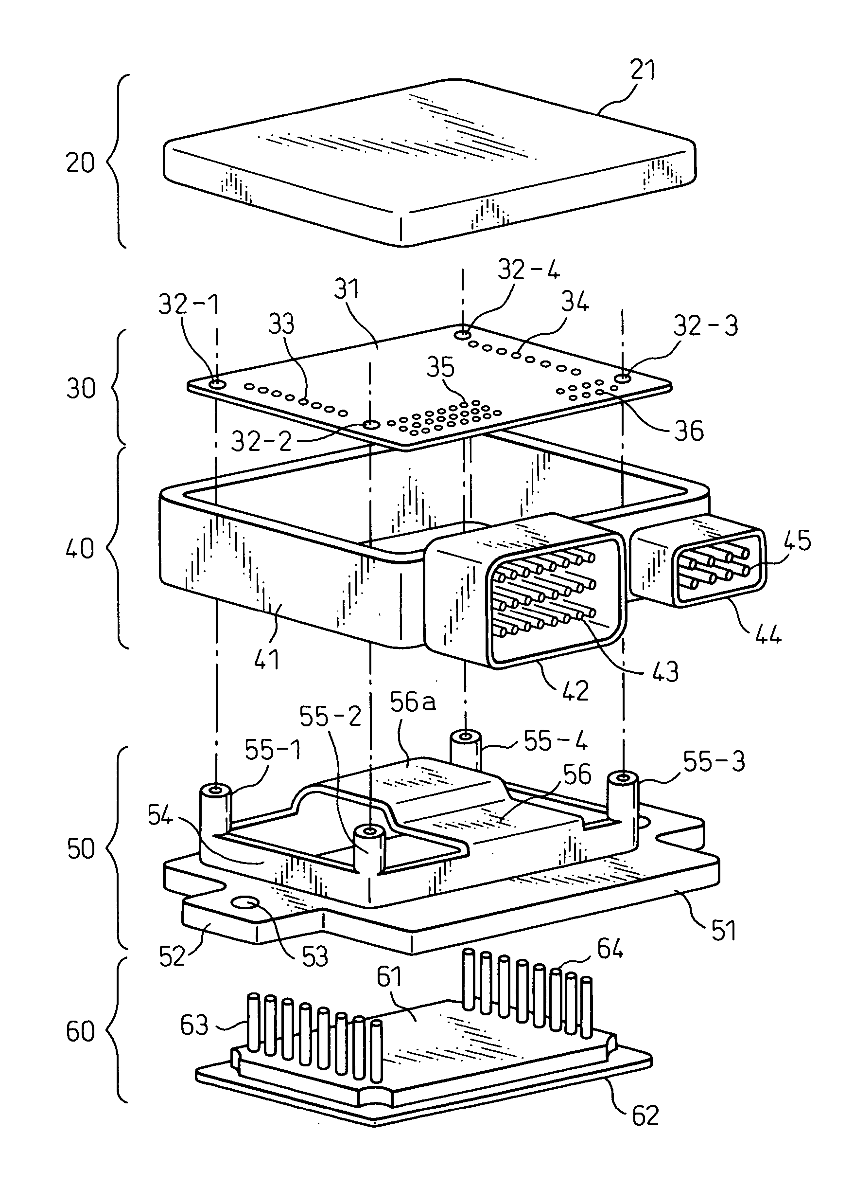
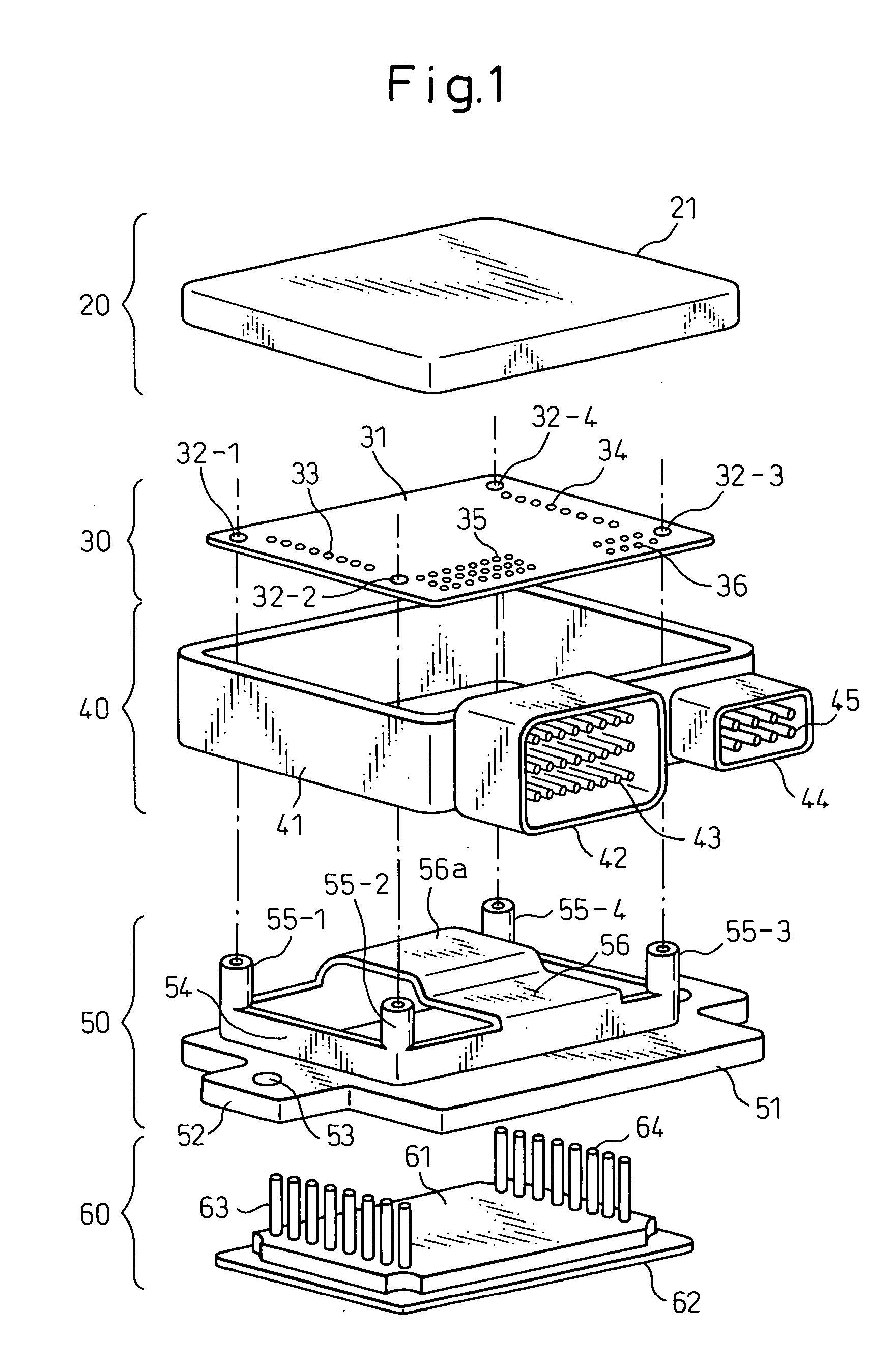
[0029] The thus constituted electronic control device can be easily assembled in a small size, and efficiently radiates the heat generated in the device, lending itself well for being easily installed even in a high-temperature environment such as in an engine compartment of an automobile and even in a narrow space.

Problems solved by technology

In the electronic control device of this constitution, the connector-integrated resin casing assumes a complex structure which is difficult to mold and assemble.
In particular, as the connectors become large and the number of storage units increases, it becomes difficult to arrange the connectors on the same side surface of the connector-integrated resin casing 2.
However, if the connectors are not mounted on the same side surface, it becomes difficult to lay the harness which requires an increased space for mounting.
Besides, the cost of production is driven up due to the use of water-proof packings between the resin casing and the closure, and between the resin casing and the heat sink.
Therefore, parts of the circuit units must be electrically connected to the connectors, and a large amount of wiring must be laid between the circuit units.
The size of the work cannot be increased.
Therefore, the cost of production becomes high.
Besides, since only limited space is available for installing electronic equipment, there is no means to realize the electronic control unit itself in a small size.
This, however, results in an increase in the size of the unit which is against the requirement for decreasing the size.
The electronic control device is too bulky to be mounted in a narrow space such as in an engine compartment.

Method used


Image

  • Electronic control device
  • Electronic control device
  • Electronic control device

Examples


Embodiment Construction

[0047] An embodiment of the electronic control device according to the invention will now be described with reference to the drawings. Before describing the electronic control device of this embodiment, however, described below is an electronic control device according to a prior art on which the electronic control device of this embodiment is based to clarify the feature and effect of this embodiment.

[0048]FIG. 16 schematically illustrates the constitution of an electronic control device disclosed in Japanese Unexamined Patent Publication (Kokai) No. 2001-323848.

[0049] A major portion working as an electronic control device 1 is accommodated in a connector-integrated resin casing 2 with which a connector casing is integrally formed. A data-receiving connector 3 and power supply connectors 4, 5 are provided being grouped into one on the side surface of the connector-integrated resin casing 2. Therefore, the electric connection of the electronic control device 1 to an external unit...


PUM


Abstract

An electronic control device enabling heat generated by a power module to be favorably radiated even in a high-temperature condition in an engine compartment. The unit includes a casing accommodating a control circuit substrate; a die-cast mounting plate forming a control circuit substrate support portion, a frame-like fitting member and an external mounting portion integrally together; and a metal substrate on which a power module is adhered. When the mounting plate is mounted on the wall of a transmission and the metal substrate is fitted in the opening in the bottom surface of the frame-like fitting member, a mounting surface in nearly the same plane is formed by the lower surface of the mounting plate and by the lower surface of the metal substrate permitting heat from the power module to be radiated to the wall.

Description

BACKGROUND OF THE INVENTION [0001] 1. Field of the Invention [0002] The present invention relates to an electronic control device mounted on a vehicle such as an automobile and, specifically, to an electronic control device used in a high-temperature environment. More particularly, the invention relates to an electronic control device which favorably radiates heat generated by a control circuit board and a power module even in a high-temperature environment such as in an engine compartment. [0003] 2. Description of the Related Art [0004] A plurality of electronic control devices have heretofore been mounted as a single unit on a vehicle such as an automobile to individually control the installed devices such as engine and the like. Each electronic control device comprises a control circuit unit including a microcomputer which executes logical control operations based upon the electronic data detected by the sensors, and a drive circuit unit which controls an electric power supply to...

Claims


Application Information

Patent Timeline
IPC IPC(8): H05K1/14H05K3/00H05K3/34H05K5/00H05K7/20
CPCH05K1/144H05K7/20854H05K3/3447H05K3/0058
Inventor WATANABE, HIROMICHISUGIURA, SHINICHIYASUHARA, TAKAFUMIMORIMUNE, KATSUFUMIKAINO, HIDEAKIWADA, NOBUHIROOOHARA, MASATSUGU
Owner FUJITSU GENERAL LTD
Learn More