Optical disk apparatus and control method therefor

a technology of optical disk and control method, which is applied in the field of optical disk apparatus, can solve the problems of impracticality, difficulty and impracticality in setting the sil at a distance, and achieve the effect of reducing time, preventing the initial speed of the optical head, and reducing the tim

Inactive Publication Date: 2005-09-01
SONY CORP
View PDF7 Cites 34 Cited by
  • Summary
  • Abstract
  • Description
  • Claims
  • Application Information

AI Technical Summary

Benefits of technology

[0020] According to the embodiment of the present invention, the initial speed of the head can be set at nearly zero in the condition in which the head is positioned at the first distance from the disk, that is, in the near-field. Thus, disturbance due to the initial speed can be prevented. Consequently, the collision of the optical head with the optical disk can be surely prevented while reducing time, which is taken to cause the head to move to a target position in a near-field region, as much as possible.
[0021] As above-mentioned, according to the embodiments of the present invention, the collision of the head with the disk can be surely prevented while reducing time, which is taken to cause the head to move to a target position in the near-field region, as much as possible.

Problems solved by technology

However, the method described above may be impractical, because time taken to realize a target gap is long unless the initial position of the SIL is set to be close to the disk.
Thus, it is difficult and impractical to set the SIL at a position located at a distance, which is equal to or less than 200 nm, without gap control.

Method used


Image

  • Optical disk apparatus and control method therefor
  • Optical disk apparatus and control method therefor
  • Optical disk apparatus and control method therefor

Examples


Embodiment Construction

[0037] Hereinafter, an embodiment of the present invention is described with reference to the accompanying drawings.

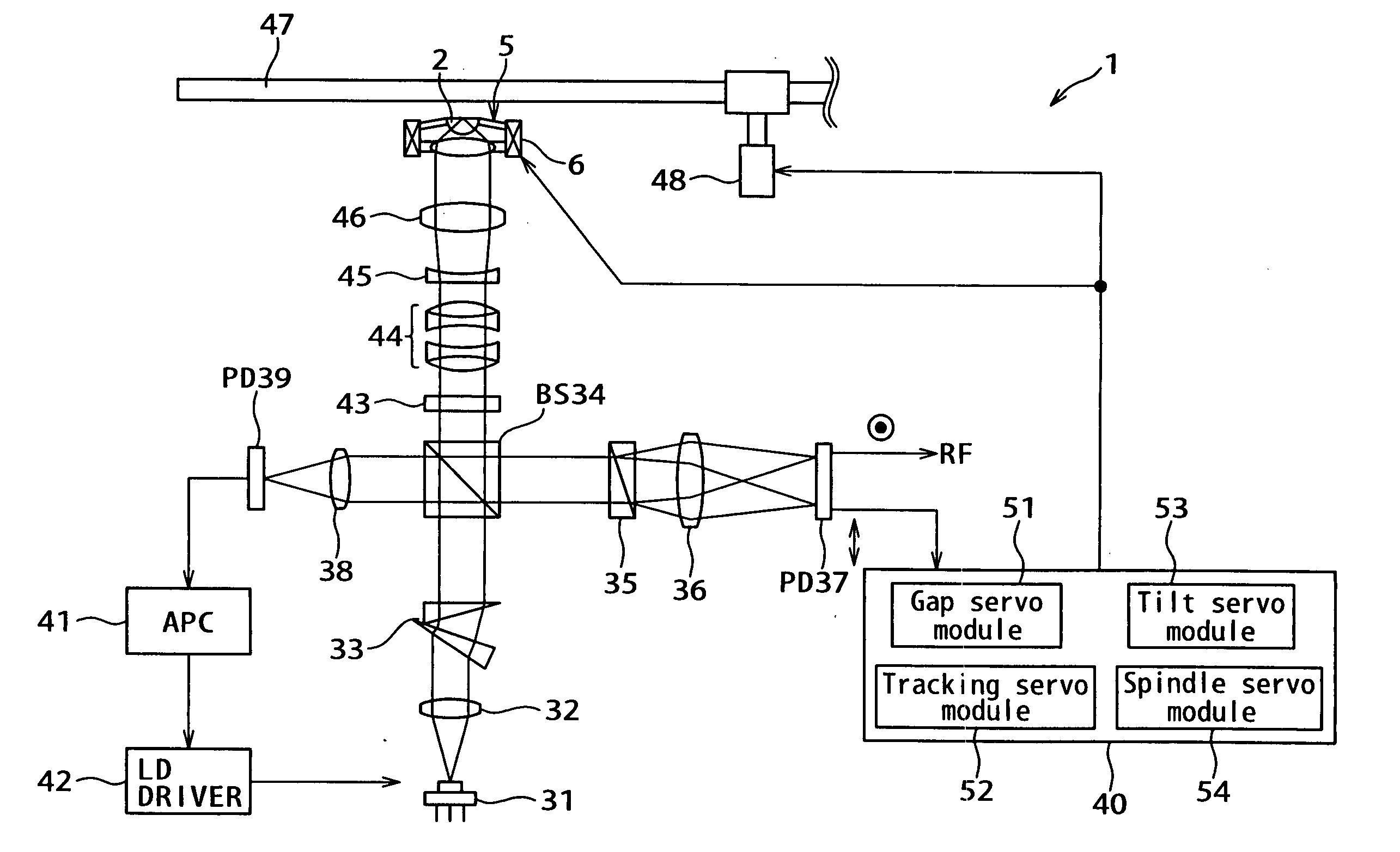
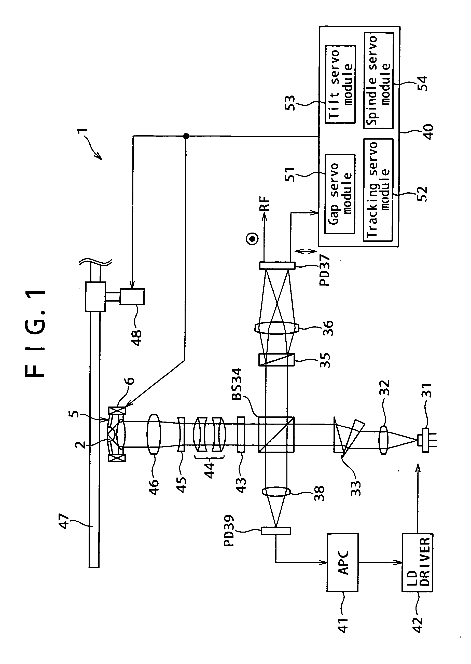
[0038]FIG. 1 is a diagram illustrating the configuration of an optical disk apparatus according to an embodiment of the present invention. The optical disk apparatus 1 has a laser diode (LD) 31 serving as a light source. The optical disk apparatus 1 further has collimator lenses 32 and 45, an anamorphic prism 33 for shaping laser light, a beam splitter (BS) 34, a quarter-wave plate (QWP) 43, a chromatic aberration correction lens 44, a laser-beam expanding lens 45, a Wollaston prism 35, condensing lenses 36 and 38, and an optical head 5. Furthermore, the optical disk apparatus 1 has photodetectors (PDs) 37 and 39, an automatic power controller 41, an LD driver 42, a servo control system 40, and a spindle motor 48.

[0039] The Wollaston prism35 includes two subprisms. Light having been incident upon this Wollaston prism 35 is polarized and split into output light beams ...


PUM

PropertyMeasurementUnit
distanceaaaaaaaaaa
distanceaaaaaaaaaa
lengthaaaaaaaaaa

Abstract

An optical apparatus includes: a light source outputting light; a head disposed so as to face a disk on which a signal is recordable, the head being capable of condensing a light from the light source onto the disk as near-field light; an distance adjusting mechanism adjusting a distance between the head and the disk; first control means for causing the head to approach the disk and controlling the head to nearly stop at a position where a distance from the disk is a first distance at which the light is condensed on the disk by the head as the near-field light; detection means for detecting if the distance is the first distance; and second control means for controlling the distance adjusting mechanism based on the detected signal so as that the distance is a second distance under near-field light condition.

Description

CROSS REFERENCES TO RELATED APPLICATIONS [0001] The present invention contains subject matter related to Japanese Patent Application JP 2004-012073 filed in the Japanese Patent Office on Jan. 20, 2004, the entire contents of which being incorporated herein by reference. BACKGROUND OF THE INVENTION [0002] 1. Field of the Invention [0003] The present invention relates to an optical disk apparatus for performing at least one of recording and reproducing of signals by using near-field light, and to a control method therefor. [0004] 2. Description of the Related Art [0005] In recent years, to enhance a recording density at which signals are recorded on an optical disk by using laser light, there has been proposed an optical disk apparatus that records or reproduces signals by using near-field light. In the optical disk on which signals are recorded by using near-field light, it is necessary to control the length of the gap between an optical disk and an end surface of an SIL (Solid Immer...

Claims


Application Information

Patent Timeline
Patent Type & Authority Applications(United States)
IPC IPC(8): G11B7/00G11B7/085G11B7/09G11B7/135G11B7/1387
CPCG11B7/1387G11B7/0908
Inventor ISHIMOTO, TSUTOMU
Owner SONY CORP
Why Eureka
Try Eureka