Radio relay system, radio relay apparatus, and radio relay method

Inactive Publication Date: 2005-09-01
NTT DOCOMO INC
View PDF6 Cites 63 Cited by
  • Summary
  • Abstract
  • Description
  • Claims
  • Application Information

AI Technical Summary

Benefits of technology

[0017] The present invention has been conceived in response to one or more of the problems of the related art, and its first object is to provide a radio relay system, a radio relay appa

Problems solved by technology

In establishing radio communication, when the distance between a transmitting apparatus and a receiving apparatus is long, or when an obstacle lies between a transmitting apparatus and a receiving apparatus, for example, sufficient reception power may not be secured.
As a result, the communications quality may be significantly degraded.
In the radio relay system as is described above that uses a direct relay method, when a direct wave is present that is to be received by a receiving apparatus directly from a transmitting apparatus without being relayed by a radio relay apparatus, unnecessary fading may occur.
Thereby, the application of the conventional radio relay method may not always lead to improvement in the communications quality; in fact, in some cases, a degradation of communications quality may occur as a result of applying the conventional radio relay method.
Thereby, the signal power received at the receiving apparatus may be very small, resulting in a significant degradation of communications quality compa

Method used


Image

  • Radio relay system, radio relay apparatus, and radio relay method
  • Radio relay system, radio relay apparatus, and radio relay method
  • Radio relay system, radio relay apparatus, and radio relay method

Examples


first embodiment

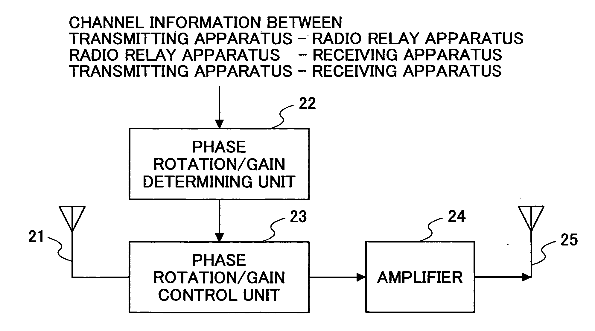
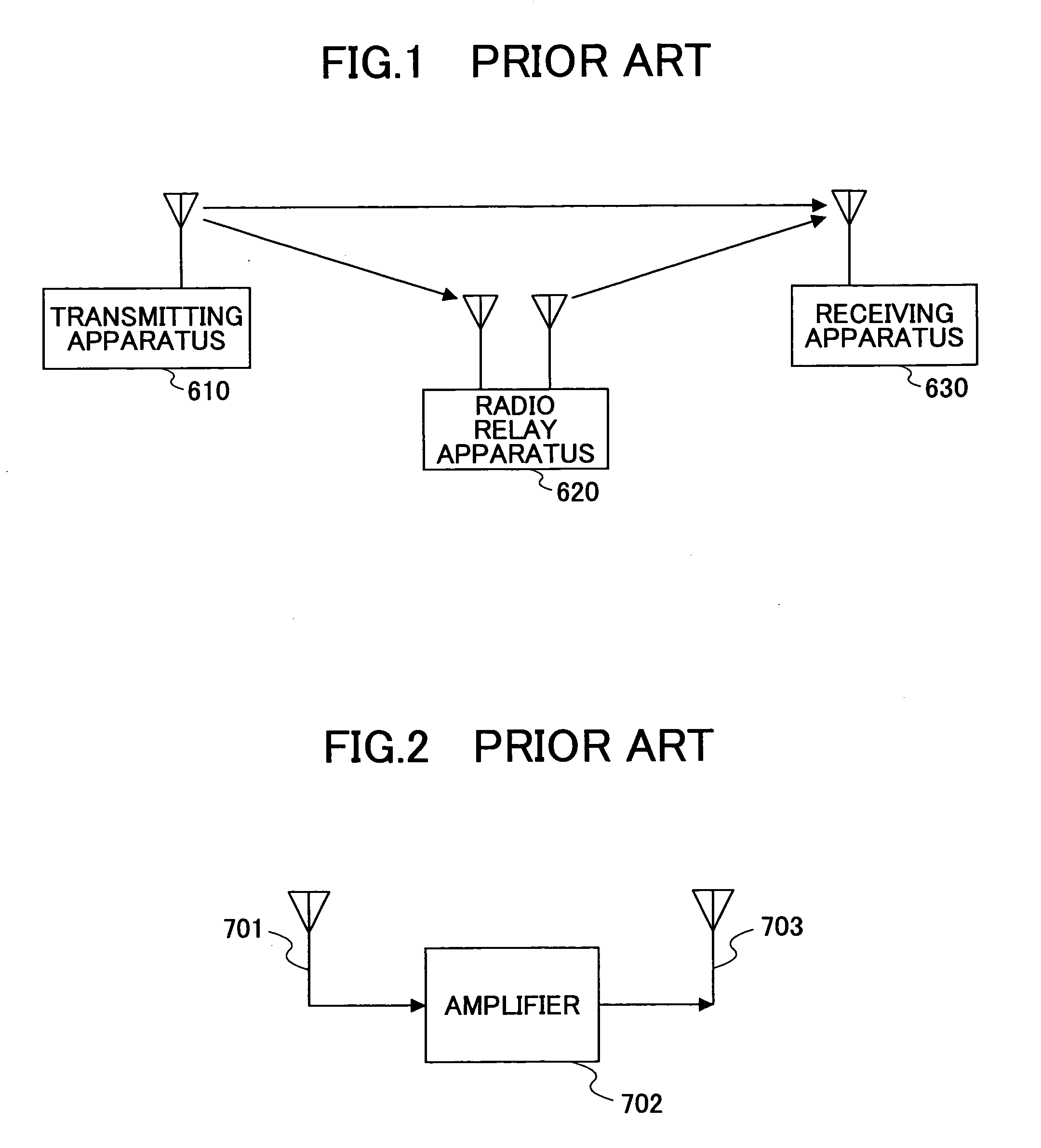
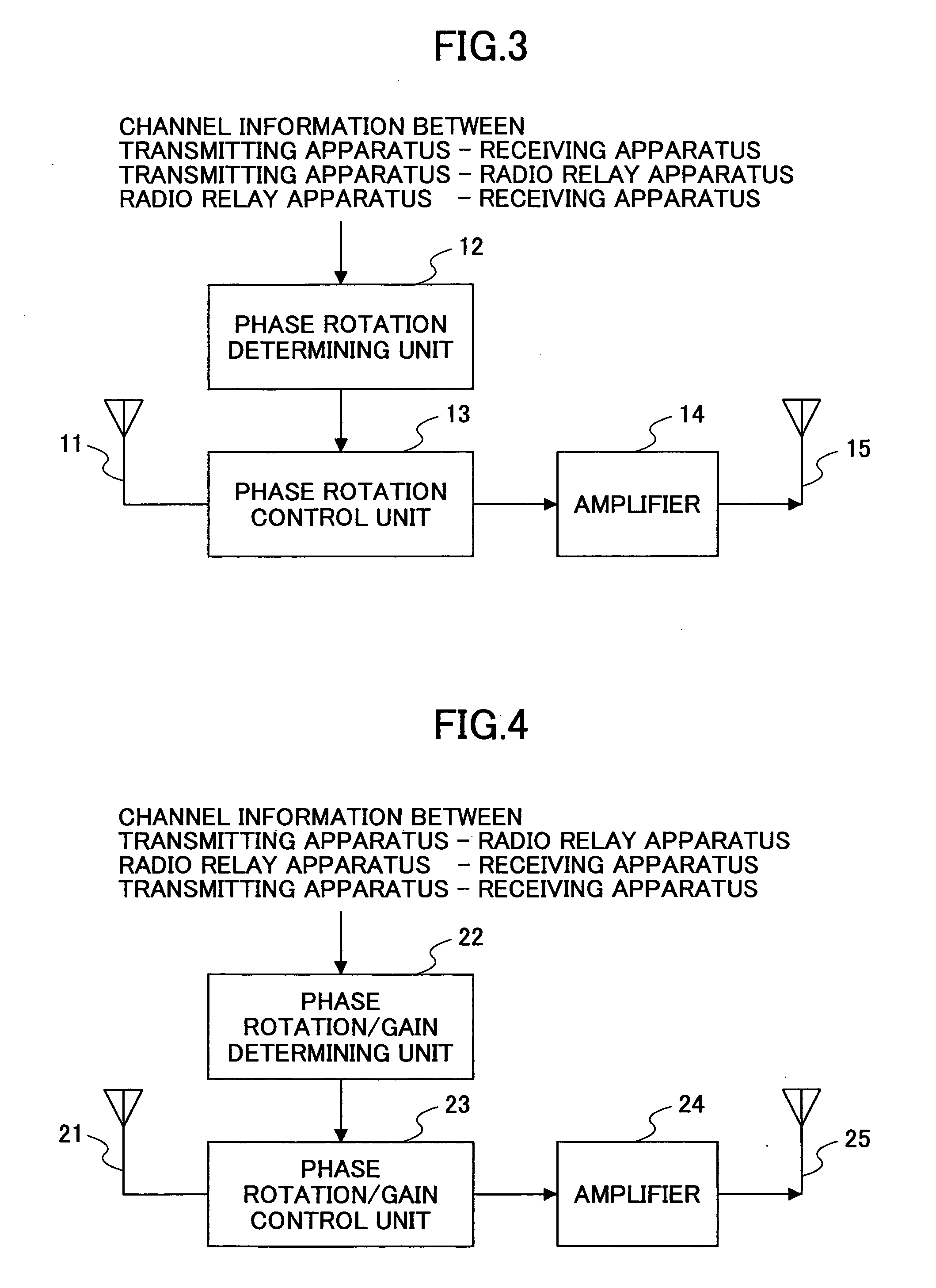
[0088] According to a first embodiment of the present invention, a radio relay apparatus as is described below is used in a radio relay system. The radio relay system of the present embodiment may have a system structure identical to that shown in FIG. 1. That is, the present radio system may include a transmitting apparatus (first wireless station), a receiving apparatus (second wireless station), and a radio relay apparatus. The radio relay apparatus may be arranged to relay a signal transmitted from the transmitting apparatus, and transmit the relayed signal using the same frequency. A signal received at the receiving apparatus may include a signal received directly from the transmitting apparatus, and a signal received via the radio relay apparatus.

[0089]FIG. 3 is a block diagram showing an exemplary configuration of a radio relay apparatus according to a first embodiment of the present invention.

[0090] According to this drawing, the radio relay apparatus includes a receiving ...

modified embodiment

[0112] According to the first embodiment, the radio relay apparatus is arranged to correct the phase difference created by fading based on channel information pertaining to the channel between the transmitting apparatus and the present radio relay apparatus, channel information pertaining to the channel between the present radio relay apparatus and the receiving apparatus, and channel information pertaining to the channel for the direct wave transmitted directly from the transmitting apparatus to the receiving apparatus. However it is noted that the present invention is not limited to such an embodiment. For example, an embodiment may be conceived in which the phase difference between the channel directly received from the transmitting apparatus by the receiving apparatus and the channel received via the radio relay apparatus is determined at the receiving apparatus, and the determined phase difference is fed back to the radio relay apparatus so that the radio relay apparatus may co...

second embodiment

[0113] According to a second embodiment of the present invention, the radio relay apparatus is provided with a multi-carrier transmission function.

[0114]FIG. 5 is a block diagram showing an exemplary configuration of a radio relay apparatus according to the second embodiment that uses the OFDM transmission scheme as the multi-carrier transmission scheme.

[0115] According to the illustrated example of FIG. 5, the radio relay apparatus includes an FFT unit 32 and an IFFT unit 35 in addition to the components of the radio relay apparatus that are illustrated in FIG. 3. The IFFT unit 35 on the transmission side may be arranged to conduct an IFFT (Inverse Fast Fourier Transform) process on plural sets of symbol data to transform the data into a time signal (OFDM transmission signal). The FFT unit 32 on the receiving side may be arranged to conduct an FFT (Fast Fourier Transform) process on the received data to transform the data into frequency signals (OFDM reception signals).

[0116] Ac...


PUM


Abstract

A radio relay system is disclosed that is capable of preventing communication degradation in a case where radio signals are relayed using the same frequency band in a mobile communication environment. The radio relay system includes a first radio station, a second radio station, and a radio relay apparatus for relaying a radio signal that is exchanged between the first radio station and the second radio station. The radio relay apparatus includes a phase correction determining unit that determines a phase correction amount of the relayed signal based on channel information pertaining to channels established between the first radio station, the second radio station, and the radio relay apparatus, and a phase correction unit that corrects the relayed signal based on the phase correction amount determined by the phase correction determining unit.

Description

BACKGROUND OF THE INVENTION [0001] 1. Field of the Invention [0002] The present invention relates generally to a radio relay system, a radio relay apparatus, and a radio relay method, and particularly to a radio relay system for establishing radio communication with a transmitting / receiving apparatus through one or more radio relay apparatuses. [0003] 2. Description of the Related Art [0004] In establishing radio communication, when the distance between a transmitting apparatus and a receiving apparatus is long, or when an obstacle lies between a transmitting apparatus and a receiving apparatus, for example, sufficient reception power may not be secured. As a result, the communications quality may be significantly degraded. In response to such a problem, a so-called radio relay transmission method (radio relay method) is conventionally used for conducting signal transmission in a broadcasting system or a mobile communication system. According to the conventional radio relay method, ...

Claims


Application Information

Patent Timeline
IPC IPC(8): H04J11/00H04B7/04H04B7/15H04B7/155H04B7/26H04J99/00H04W16/26
CPCH04B7/15535H04B7/2606H04H20/02H04L25/0224H04L5/0032H04L5/0048H04L5/0023A47J31/10A47J31/4403A47J31/46A47J31/58
Inventor FUJII, HIROMASASUDA, HIROHITOTANAKA, TETSU
Owner NTT DOCOMO INC
Why Eureka
Try Eureka