Motion estimation method and moving picture coding method

Inactive Publication Date: 2005-09-01
PANASONIC CORP
View PDF4 Cites 43 Cited by
  • Summary
  • Abstract
  • Description
  • Claims
  • Application Information

AI Technical Summary

Benefits of technology

[0024] As described above, according to the motion estimation method of the present invention, it is possible to reduce the number of times for which a reference block serving as a search center is shifted to another reference block, thereby achieving fast m

Problems solved by technology

Therefore, it is not realistic for the aforementioned information media to handle such an enormous amount of information as it is in digital form.
For example, although video phones are already in the actual use by using Integrated Services Digital Network (ISDN) which offers a transmission speed of 64 Kbits/s to 1.5 Mbits/s, it is not practical to transmit video of televisions and cameras directly through ISDN.
If all the reference blocks in a reference picture are searched, an enormous amo

Method used


Image

  • Motion estimation method and moving picture coding method
  • Motion estimation method and moving picture coding method
  • Motion estimation method and moving picture coding method

Examples


first embodiment

[0045]FIG. 3 is a block diagram showing a structure of a moving picture coding apparatus that uses a motion estimation method according to the first embodiment of the present invention.

[0046] The moving picture coding apparatus is comprised of a picture memory 101, a prediction residual coding unit 102, a coded stream generation unit 103, a prediction residual decoding unit 104, a picture memory 105, a motion vector estimation unit 106, a motion compensated coding unit 107, a difference calculation unit 108, an addition unit 109, and switches 110 and 111.

[0047] The picture memory 101 holds a moving picture that is inputted on a picture-by-picture basis in display order.

[0048] The motion compensated coding unit 107 determines a coding mode used for each block, based on a motion vector estimated by the motion vector estimation unit 106, and generates predictive image data (predictive pixel values) based on the determined coding mode. For example, in the case of inter-picture predic...

second embodiment

[0085] In the first embodiment, the end judgment unit 204 judges whether or not motion estimation should be ended, but the second embodiment presents the case where judgment of whether to end motion estimation or not is made by use of a counter, in addition to end judgment made by the end judgment unit 204.

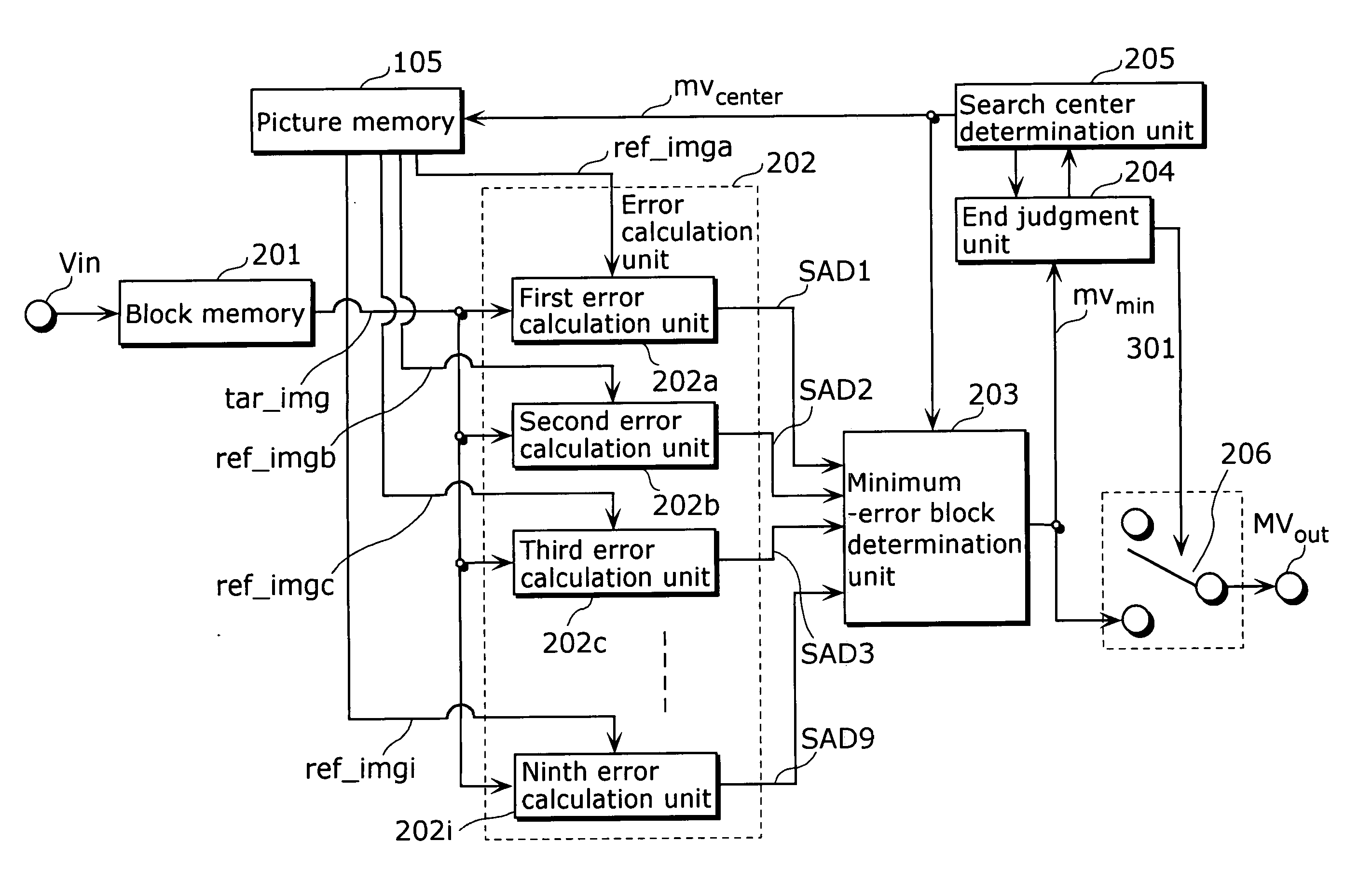
[0086]FIG. 10 is a block diagram showing another structure of the motion estimation unit 106 shown in FIG. 3. In FIG. 10, components and the like that are the same as those illustrated in FIG. 4 are assigned the same reference numbers, and descriptions thereof will not be repeated.

[0087] The motion estimation unit 106 includes a counter 301, in addition to the components presented in the first embodiment. The counter 301 counts the number of times for which motion vectors mvmin are outputted from the minimum-error block determination unit 203, i.e., the number of times for which a reference block serving as a search center has been updated. Then, the counter 301 turns the switch...

third embodiment

[0094] Furthermore, if a program for implementing the motion estimation method as shown in the aforementioned embodiments is recorded on a recording medium such as a flexible disk, it becomes possible to easily perform the processing presented in the above embodiments in an independent computer system.

[0095]FIGS. 12A, 12B, and 12C are diagrams for illustrating the case where the motion estimation method according to the above embodiments is carried out in a computer system, using a program that is stored in a recording medium such as a flexible disk.

[0096]FIG. 12B shows an external view of a flexible disk viewed from the front, its schematic cross-sectional view, and the flexible disk itself, while FIG. 12A illustrates an example physical format of the flexible disk as a recording medium itself. The flexible disk FD is contained in a case F, and a plurality of tracks Tr are formed concentrically on the surface of the flexible disk FD in the radius direction from the periphery, eac...


PUM


Abstract

The motion vector estimation unit (106) is comprised of: an error calculation unit (202) that calculates errors SAD1 to SAD9 that are differences between the current block data tar_img and the respective neighboring reference block data ref_img; a minimum-error block determination unit (203) that determines, as a minimum-error block, a reference block that includes the smallest error of all the errors SAD1 to SAD9, and outputs a motion vector mvmin corresponding to the position of the determined minimum-error block; an end judgment unit (204) that judges whether or not the motion estimation should be ended; and a search center determination unit (205) that determines, as a reference block serving as the next search center, a reference block that is two pixels or more away from the current search center, according to the position of the minimum-error block.

Description

BACKGROUND OF THE INVENTION [0001] (1) Field of the Invention [0002] The present invention relates to a motion estimation method that is used in a picture coding method and the like for efficiently compressing a moving picture signal by use of the correlation between pictures. [0003] (2) Description of the Related Art [0004] In the age of multimedia which integrally handles audio, video and other pixel values, existing information media, i.e., newspaper, magazine, television, radio, telephone and other means through which information is conveyed to people, have recently come to be included in the scope of multimedia. Generally, multimedia refers to something that is represented by associating not only characters, but also graphics, audio, and especially pictures and the like together. However, in order to include the aforementioned existing information media into the scope of multimedia, it appears as a prerequisite to represent such information in digital form. [0005] However, when...

Claims


Application Information

Patent Timeline
IPC IPC(8): H04N5/14H04N7/12H04N7/26H04N7/36H04N7/50
CPCH04N5/145H04N21/41422H04N19/533H04N19/61H04N21/6143A47J27/002A47J36/06A23L11/70
Inventor KADONO, SHINYASHIBAHARA, YOUJI
Owner PANASONIC CORP
Why Eureka
Try Eureka