Shaped blurring of images for improved localization of point energy radiators

a technology of point energy radiators and blurring, applied in the field of metal systems, can solve the problems of reducing the signal-to-noise ratio, reducing the intensity of the image, and undesirable poor focus or intentional blurred image, so as to improve the sub-pixel accuracy in the determination and enhance the computing

Inactive Publication Date: 2005-09-01
CONCEPTUAL ASSETAB
View PDF6 Cites 14 Cited by
  • Summary
  • Abstract
  • Description
  • Claims
  • Application Information

AI Technical Summary

Problems solved by technology

A poorly focused or intentionally blurred image is considered undesirable, except perhaps for artistic purposes.
However, sharp focus over a larger depth of field requires the smallest aperture (largest “f / stop number”) allowed by the lighting and exposure time constraints.
Smaller apertures have the disadvantage of decreasing the intensity of the image (thereby lowering the signal-to-noise ratio) and of increasing the effects of diffraction.
It may therefore seem counter-intuitive that poorer focus might improve the determination of the location of the image of a point-like radiator.
This is ideal for most imaging purposes, but all the information available to determine the image's location within that pixel has been lost.
Note also that linear interpolation does not correctly identify the location of the center of a typically circular image divided across the two pixels.)
Besides the higher cost of such a camera, the high pixel count normally increases the time to find and process the image, and therefore it reduces system throughput.
Such correlation filtering by itself is only effective at the pixel level, and is not intended for sub-pixel localization.
The disadvantage of the large retro-reflective radiator is that the centroid is affected by non-uniform reflectivity from the parts of the radiator—perhaps because of dirt, stains, oil, or liquids accumulated on the radiator.
Non-uniform lighting or non-uniform material characteristics may also affect the sub-pixel accuracy of the centroid.
Alternatives to using the centroid suffer the a similar problem—such as determining the center of the best-fit circle matched with the boundary of the image.
However, to recover the scene, intense computation (2-d correlations or Fourier transforms) are required, and the recovered image of a point energy radiator might not necessarily have the desired characteristics for recovery of accurate, sub-pixel positional information.
Unfortunately, intense computation involved-particularly for two dimensional pixel arrays-limits the throughput speed.

Method used


Image

  • Shaped blurring of images for improved localization of point energy radiators
  • Shaped blurring of images for improved localization of point energy radiators
  • Shaped blurring of images for improved localization of point energy radiators

Examples


Embodiment Construction

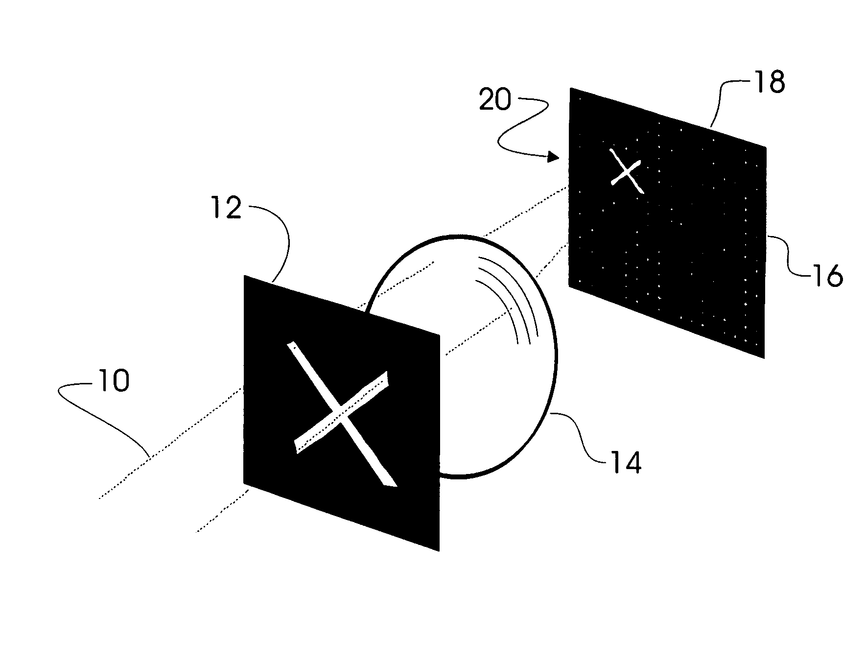
[0040] The invention in many respects is similar to a standard digital or video camera—one or more of which are part of a metrology system accurately determining the location(s) of one or more tiny radiators of light (or other energy). Multiple such energy radiators attached to a (rigid) body can then be used to track the location and orientation of the body or of distinguished parts or points of the body—preferably in real time. The present invention provides an improvement to such a system. The invention's principal elements are depicted in the simplified perspective drawing of FIG. 7.

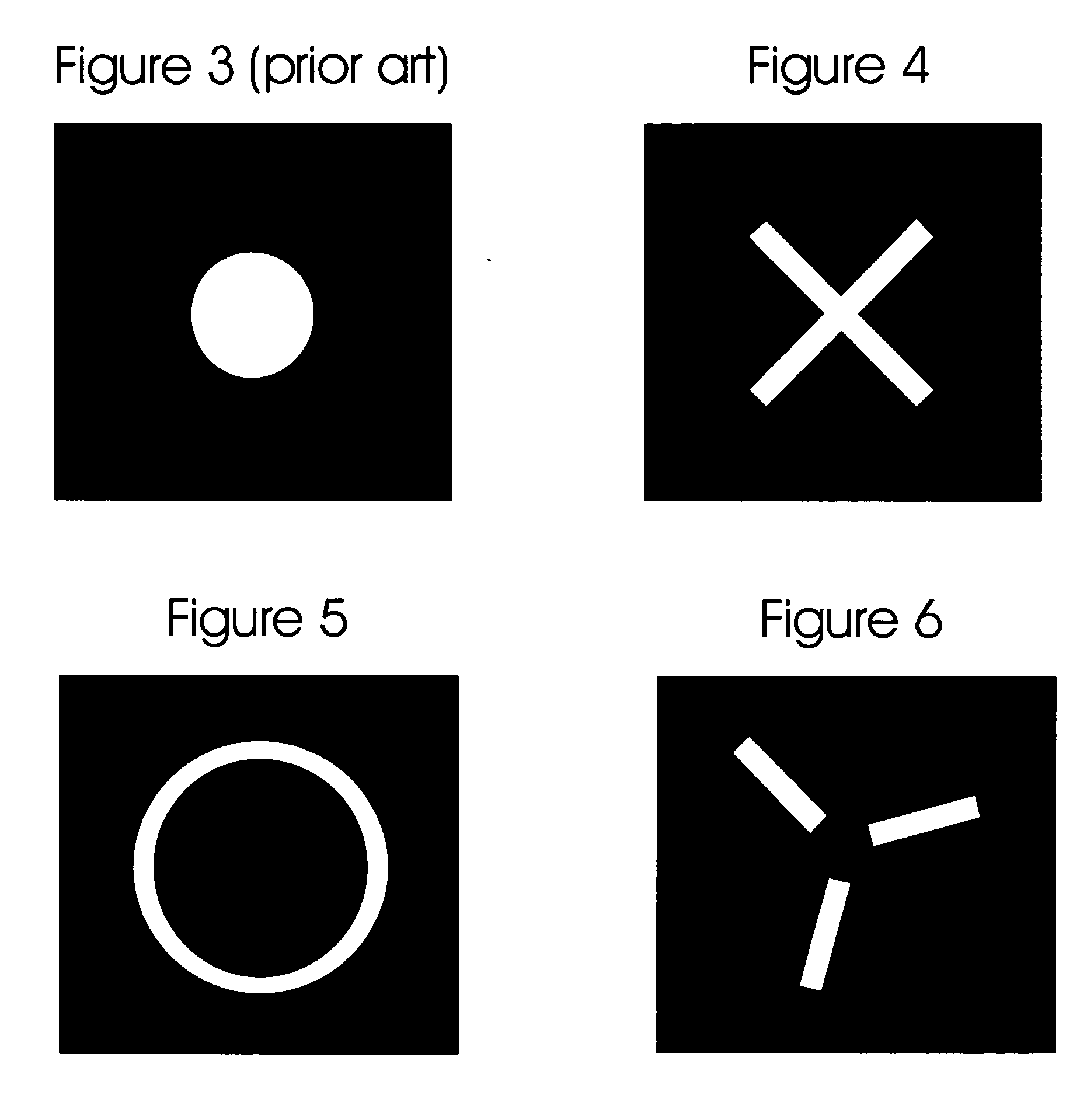
[0041] The invention according to the preferred embodiment uses a aperture 12 such as one of those shown in FIGS. 4 through 7 and preferably uses a lens system 14 which introduces a controlled amount of blur or consistent aberration into the image 20 of a point radiator of energy. This blurring may be accomplished simply by focusing the lens for a distance nearer than the volume in which the point r...


PUM


Abstract

The method of this invention, and any apparatus which implements it, improves the accuracy of determining the sub-pixel location of the image of a point-like radiator of energy (typically light). This method distributes the image of a point radiator of energy over detector pixels such that the number of image pixels with high intensity gradients is maximized, while it minimizes the energy wasted on pixels with low intensity gradients, which contribute little to the computation of the sub-pixel location of the image. By improving such accuracy in each of one or more cameras, the accuracy of deriving the spatial location of the energy radiator improves also.

Description

CROSS-REFERENCE TO RELATED APPLICATIONS [0001] not applicable FEDERALLY SPONSORED RESEARCH [0002] not applicable SEQUENCE OR PROGRAM LISTING [0003] not applicable FIELD OF INVENTION [0004] This invention relates to an improvement relating to a metrology system which determines the location of at least one point-like radiator of energy in a coordinate space using one or more digital or video cameras or other such imaging sensors which employ 2-dimensional arrays of pixels. BACKGROUND [0005] Generally in photography and in machine vision, one wants the sharpest image of a subject possible within hardware cost and feasibility constraints for a (digital or video) camera. A poorly focused or intentionally blurred image is considered undesirable, except perhaps for artistic purposes. Sharp focus usually requires a precision multi-element lens. For imaging and tracking radiators within a large 3-dimensional volume we also seemingly would desire good focus within a large depth of field. How...

Claims


Application Information

Patent Timeline
Patent Type & Authority Applications(United States)
IPC IPC(8): G02B5/00G02B27/09G06K9/36
CPCG02B5/005G02B27/0988G02B27/0927
Inventor SCHULZ, WALDEAN A.
Owner CONCEPTUAL ASSETAB
Why Eureka
Try Eureka