Cleaning device and image forming apparatus

a cleaning device and image forming technology, applied in electrographic process apparatus, instruments, optics, etc., can solve the problems of reducing the transfer efficiency of toner images from the image bearing body to the recording medium, and achieve the effect of increasing the rotational speed of the collection roller, and improving the collection performance of the collection roller

Active Publication Date: 2005-09-01
KONICA MINOLTA INC
View PDF9 Cites 14 Cited by
  • Summary
  • Abstract
  • Description
  • Claims
  • Application Information

AI Technical Summary

Benefits of technology

[0012] The rotational direction of the collection roller is in the forward direction relative to the rotation direction of the cleaning brush. This prevents the brush fibers of the cleaning brush from curling or inclining permanently. Thus, this avoids that the permanent inclination in the brush fibers reduces the outer diameter of the cleaning brush so as to degrade the cleaning performance. The circumferential speed ratio of the collection roller to the cleaning brush greater than one and smaller than two achieves efficient removing of the toner from the image bearing body. Further, in the case that a fixed scraper for removing the toner from the collection roller is arranged, wear at a tip of the scraper is suppressed. Thus, according to the first aspect of the present invention, the brush fibers of the cleaning brush is prevented from curling or inclining permanently, and the scraper is protected from tip wear. This permits efficient toner removal from the image bearing body even after the apparatus has been used for a long time. Further, this configuration does not need a plurality of collection rollers, resulting in simple configuration of the cleaning device.
[0026] Further, the controller preferably sets the rotational speed of the collection roller at higher speed for a predetermined time period when the first cleaning operation is performed after factory shipment. When the first cleaning operation is performed after factory shipment, the brush fibers of the cleaning brush curl or incline permanently in the portions contacting with the intermediate transfer member and the collection roller. Thus, owing to that the rotational speed of the collection roller is set at higher speed when the first cleaning operation is performed after factory shipment, the permanent inclination is corrected in the brush fibers, so that the cleaning performance is recovered.

Problems solved by technology

This reduces the transfer efficiency of a toner image from the image bearing body to the recording medium.

Method used


Image

  • Cleaning device and image forming apparatus
  • Cleaning device and image forming apparatus
  • Cleaning device and image forming apparatus

Examples


first embodiment

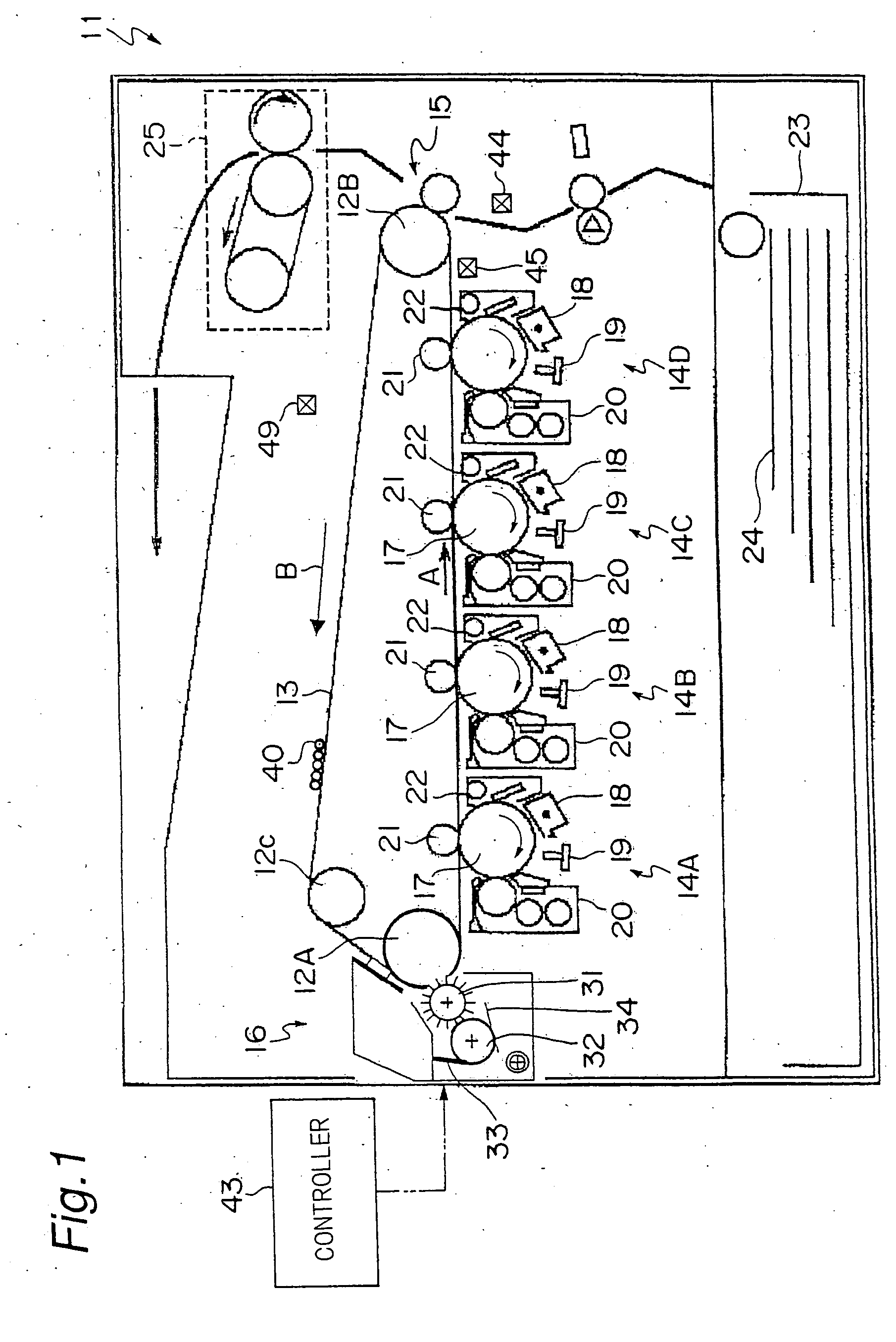
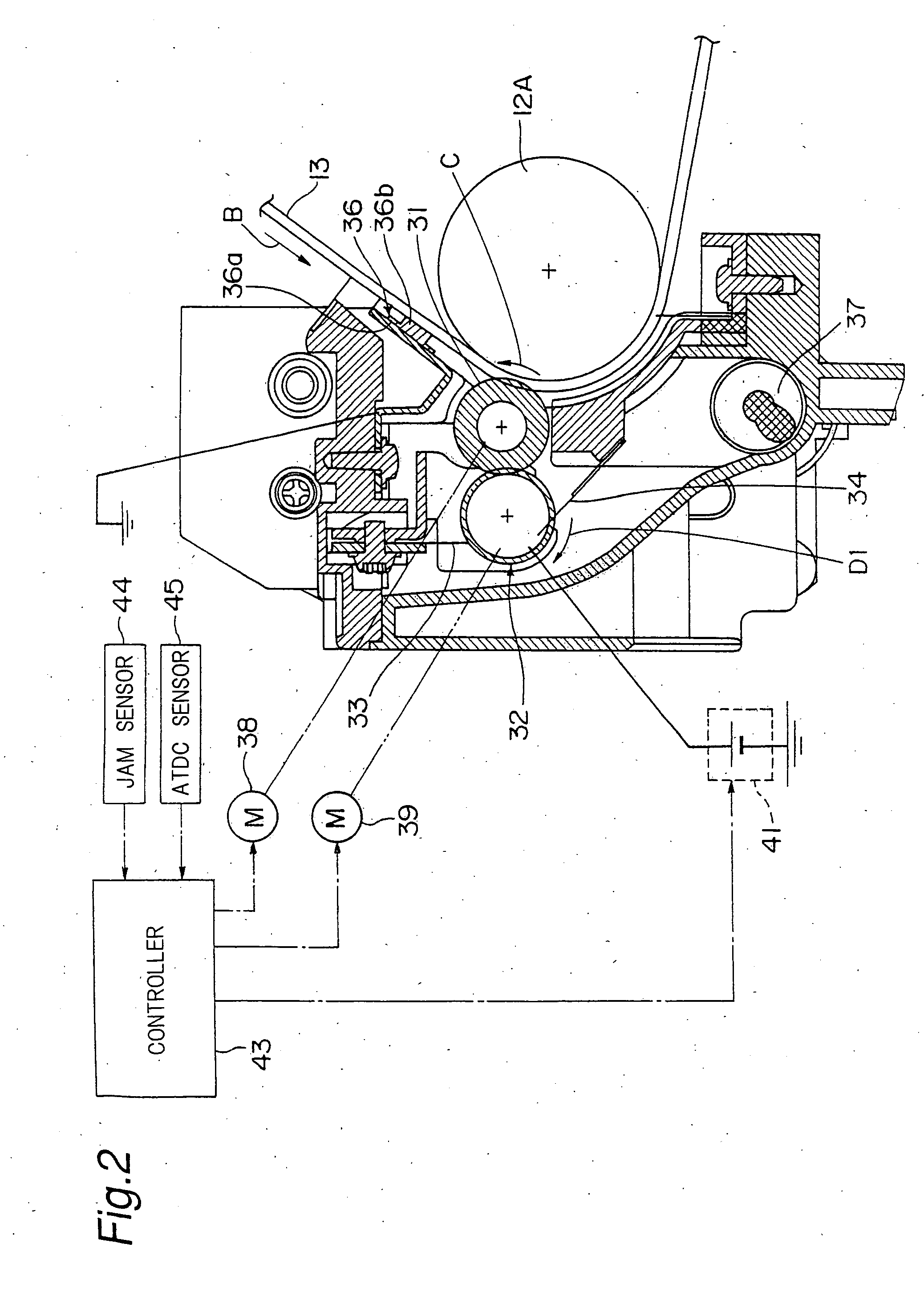
[0054]FIG. 1 shows a laser printer 11 of tandem process type serving as an image forming apparatus according to an embodiment of the present invention. In the present embodiment, a normal charging polarity of toner is assumed to be negative.

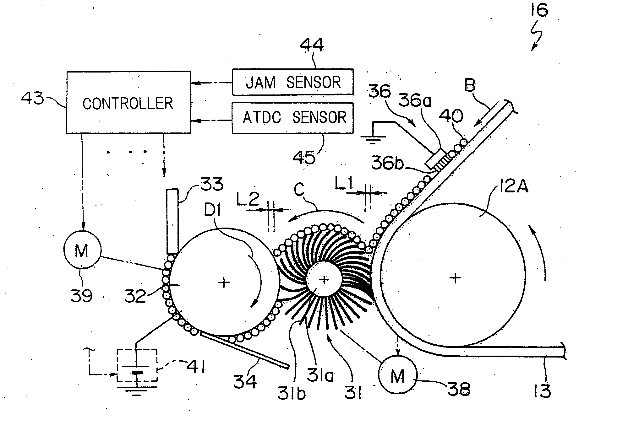
[0055] An intermediate transfer belt 13 (referred to as a transfer belt hereinafter) stretched on support rollers 12A, 12B, and 12C is forwarded in a direction indicated by an arrow B by rotation of the support rollers 12A-12C. Around the transfer belt 13, there are disposed first through fourth image forming units 14A-14D, a secondary transfer device 15, and a secondary cleaning device 16 (referred to as a cleaning device hereinafter).

[0056] The image forming units 14A-14D respectively transfers images of yellow (Y), magenta (M), cyan (C), and black (Br) onto the transfer belt 13. The image forming units 14A-14D have the same structure with each other, and each unit comprises a charging device 18, an exposure device 19, a developing device 20,...

second embodiment

[0086] Described below is second embodiment of the invention shown in FIGS. 12A and 12B. A collection roller 32, a scraper 33, and a seal member 34 are supported on a common a support member 47. The support member 47 can move reciprocally as indicated by an arrow E in the horizontal direction of the figure by a drive mechanism 48 provided with a solenoid and a transmission mechanism. Thus, the collection roller 32 can move between a first position where the collection roller 32 is in contact with the cleaning brush 31 as shown in FIG. 12A and a second position where the collection roller is spaced to the cleaning brush 31 as shown in FIG. 12B. In the present embodiment, a plunger of the solenoid the drive mechanism 48 is located at a retracted position when the power is off state. At this time, the support member 47 is located at such a position that the collection roller 32 is spaced to the cleaning brush 31 as shown in FIG. 12B. On the contrary, when the power is on state, the plu...

third embodiment

[0090] Described below is third embodiment of the invention shown in FIGS. 14A and 14B. In the present invention, a motor of a drive mechanism 39 can rotate two ways in the forward and the reverse directions. Thus, the collection roller 32 can rotate not only in the forward direction (arrow D 1) relative to the cleaning brush 31 as shown in FIG. 14A, but also in the reverse direction (arrow D2) relative to the cleaning brush 31 as shown in FIG. 14B. The controller 43 controls the drive mechanism 39 to set the rotational direction of the collection roller 32. Further, a humidity sensor 49 for detecting the humidity inside the laser printer 11 is provided in the laser printer 11.

[0091] Referring to FIG. 6, when the circumferential speed ratio PV1 / PV2 of the collection roller 32 with respect to the cleaning brush 31 is the same, a higher collection performance for the toner is obtained in the case that the collection roller 32 rotates in the reverse direction relative to the cleaning ...


PUM


Abstract

A secondary cleaning device has a cleaning brush, collection roller, and controller. The cleaning brush is driven by a drive mechanism and thereby rotates in a state that brush fibers thereof are contacting with a secondary transfer belt to collect toner on the secondary transfer belt. The collection roller is driven by another drive mechanism and thereby rotates in a state contacting with the cleaning brush to collect toner from the cleaning brush. The collection roller rotates in such a manner that the collection roller and the cleaning brush move in the same direction with each other at a contact area between the collection roller and the cleaning brush. The controller controls the drive mechanism such that the circumferential speed ratio of the collection roller with respect to the cleaning brush is greater than one and smaller than two.

Description

RELATED APPLICATION [0001] This application is based on Japanese Patent Application No. 2004-53844, the contents in which is incorporated herein by reference. BACKGROUND OF THE INVENTION [0002] The present invention relates to a cleaning device and an image forming apparatus. In particular, the present invention is applicable to a cleaning device provided in an image forming apparatus such as a laser printer, a copying machine, facsimile machine, and multi-function machine of these apparatuses. [0003] An image forming apparatus is provided with a cleaning device for collecting toner remaining on the surface of a photoconductor (e.g., photoconductor drum or photoconductor belt) or an intermediate transfer member (e.g., intermediate transfer belt or intermediate transfer drum) as image bearing bodies after transfer of a toner image. [0004] As shown in FIG. 18, a cleaning device is known that comprises: a cleaning brush 2 rotating with contacting to an image bearing body 1, a collectio...

Claims


Application Information

Patent Timeline
Patent Type & Authority Applications(United States)
IPC IPC(8): G03G21/10G03G15/00G03G15/16G03G21/00
CPCG03G21/0035
Inventor YAMAKI, HIDEONAKAYAMA, YASUNORINOGUCHI, HIDETOSHISHIBUYA, SATORUMORI, TOMOHIDETANAKA, YASUOHIGASHIMURA, HIDEJI
Owner KONICA MINOLTA INC
Why Eureka
Try Eureka