Container connecting metal fixture

Inactive Publication Date: 2005-09-01
MARIFIT +2
View PDF15 Cites 15 Cited by
  • Summary
  • Abstract
  • Description
  • Claims
  • Application Information

AI Technical Summary

Benefits of technology

[0048] The safety mechanism may include an inclined path declining outward formed on the joint main body, a rolling element capable of freely rolling and arranged on the inclined path, and a fitted recess formed on the shaft, and when the shaft is at the position at which it is rotatable by the articulated mechanism stretched, the inclined path of the joint main body and the fitted recess of the shaft may communicate with each other and, under this status, in the case where the safety mechanism is tilted by an angle exceeding a predetermined angle, rotation of the shaft may be prevented by fitting of the rolling element into the fitted recess.
[0049] According to this constitution, when the containers tilt under the status where they are coupled with each other, the joint main body, i.e., the safety mechanism provided on the joint main body is also tilted, the rolling elements roll along one of the tilted paths corresponding to the direction of the tilt and the rolling elements are fitted in the fitted recesses formed on the shaft facing the rolling elements. For this reason, rotation of the shaft caused by the biasing force of the spring means can be securely prevented.
[0050] The safety mechanism may include an inclined path climbing outward formed on the shaft, a rolling element capable of freely rolling arranged on the inclined path, and a fitted recess formed on the joint main body, and when the shaft is at the position at which it is rotatable by the sliding member slid, the inclined path of the shaft and the fitted recess of the joint main body may communicate with each other and, under this status, in the case where the safety mechanism is tilted joint by an angle exceeding a predetermined angle, rotation of the shaft may be prevented by fitting of the rolling element into the fitted recess.
[0051] According to this constitution, when the containers tilt under the status where

Problems solved by technology

In this case, there are problems that it is difficult to operate securely the operation knob with the tip of the elongated tool, that much time is necessary to carry out this work and that the fatigue caused by operating the heavy elongated tool is considerable.
Furthermore, in the case where the operation starts from the uppermost container, this work has a disadvantage from the viewpoint of

Method used


Image

  • Container connecting metal fixture
  • Container connecting metal fixture
  • Container connecting metal fixture

Examples


first embodiment

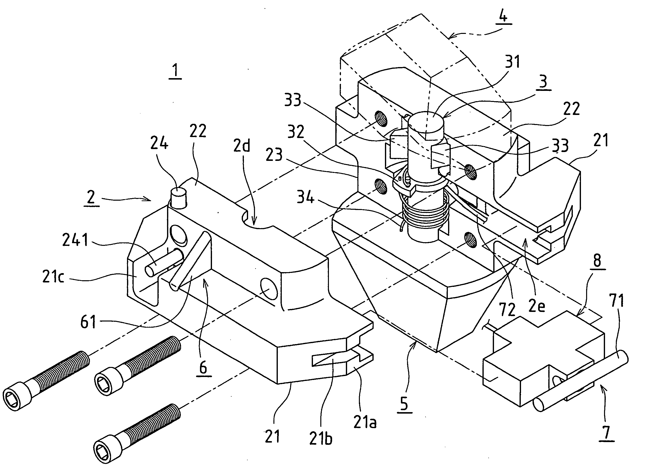
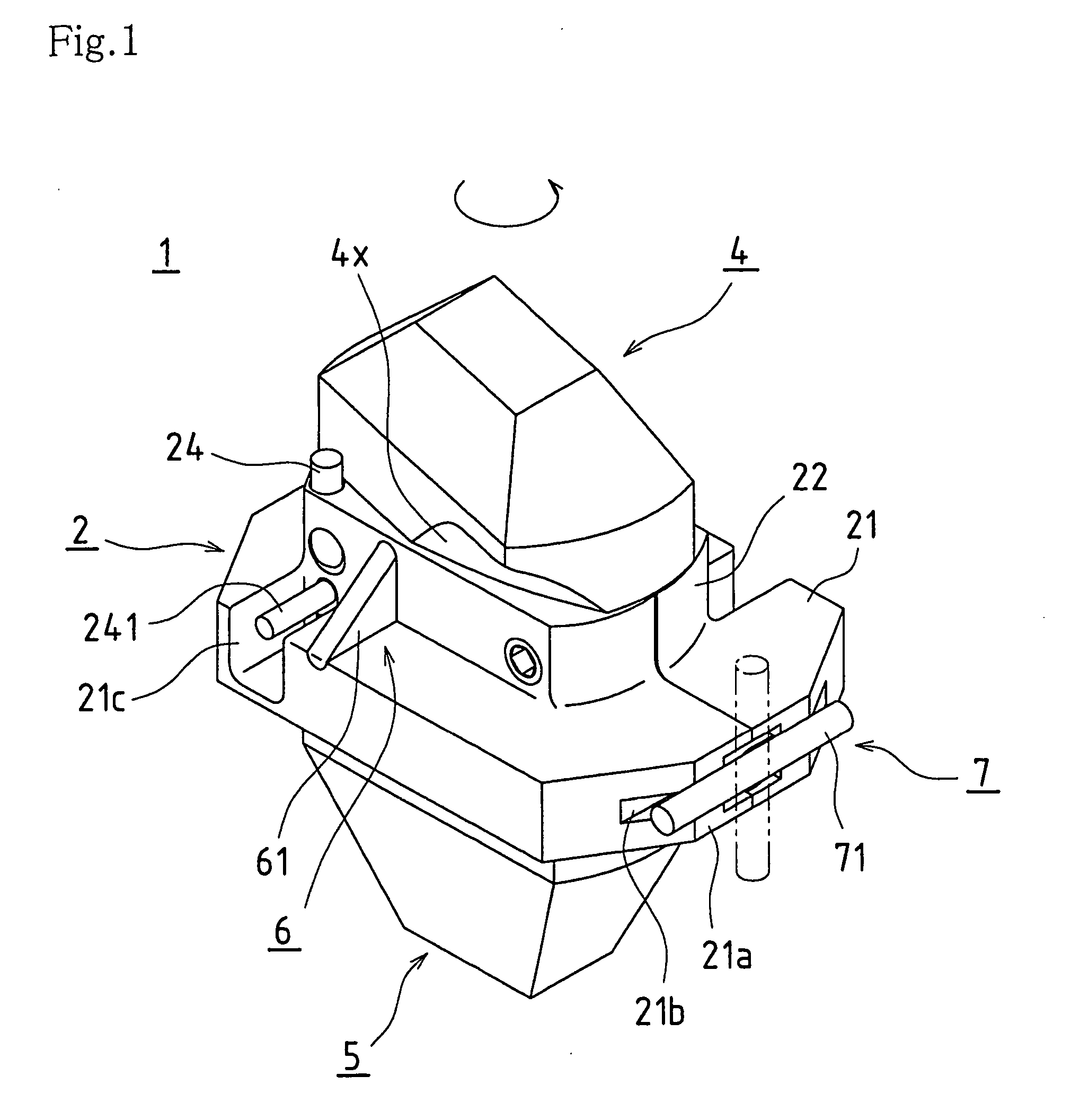
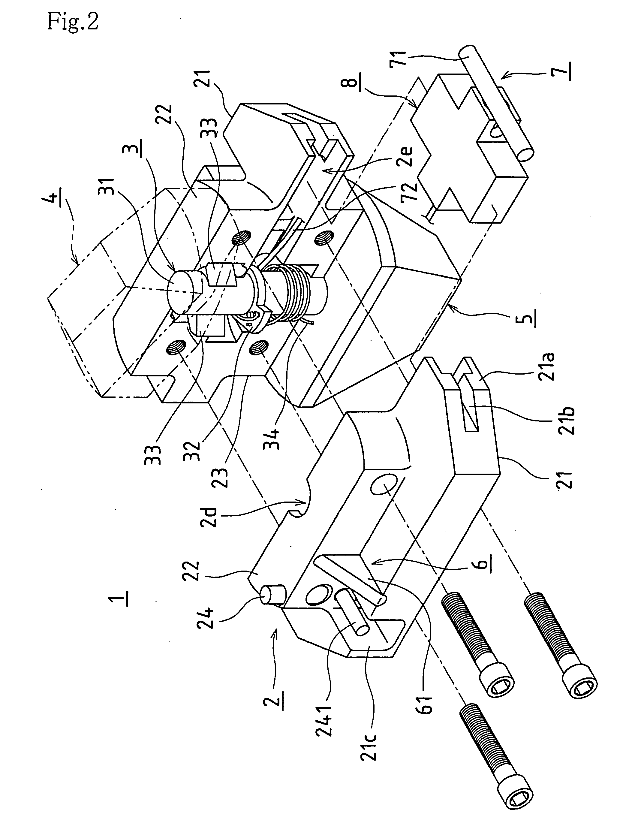
[0087]FIGS. 1 and 2 show a container coupling metal joint 1 of the invention.

[0088] This container coupling metal joint 1 comprises a joint main body 2 dividable to right and left and fastened together by a bolt as one part, a shaft 3 pivoted rotatably to the joint main body 2, an upper metal fitting 4 connected to the upper end of the shaft 3 as one part, a lower metal fitting 5 connected to the lower end of the shaft 3, a rotation mechanism 6 for rotating the shaft 3 when the load of the container Ct works on it, an operating member 7 for rotating the shaft 3, i.e., the upper metal fitting 4 and the lower metal fitting 5 and a safety mechanism 8 for limiting the rotation of the shaft 3.

[0089] The joint main body 2 comprises a main body portion 21 which is larger than the engaging aperture Fa of the corner fitting F of the container Ct, an upper fitting portion 22 and a lower fitting portion 23 respectively provided on the upper portion and the lower portion of the main body porti...

second embodiment

[0129]FIGS. 15 and 16 show the container coupling metal joint 1 of the invention.

[0130] For describing the second embodiment of the container coupling metal joint 1, the same reference numbers are given to the members same as the members constituting the first embodiment of the container coupling metal joint 1 described above. The detailed description for those members is omitted and only the rotation mechanism 6 and the safety mechanism 8 that differ from those of the first embodiment will be described.

[0131] The rotation mechanism 6 in this container coupling metal joint 1, comprises an ascending / descending member 62 provided on the main body portion 21 of the joint main body 2, being capable of being protruded and retreated and an articulated link 63, such as a chain, having a plurality of articulated points arranged below the ascending / descending member 62 in a housing space formed in the main body portion 21 of the joint main body 2, communicating with the cavity 2f. At the ea...

third embodiment

[0149] the container coupling metal joint 1 is shown in FIGS. 17 to 19.

[0150] Similarly for describing the third embodiment of the container coupling metal joint 1, the same reference numbers are given to the members same as the members constituting the first embodiment of the container coupling metal joint 1 described above. The detailed description for those members is omitted and only the rotation mechanism 6 and the safety mechanism 8 that differ from those of the first embodiment will be described.

[0151] The rotation mechanism 6 of the container coupling metal joint 1 comprises a guide path 21d formed communicating with the cavity 2f from upward to the cavity 2f, in the main body portion 21 of the joint main body 2 and a sliding member 64 slidably housed in the guide path 21d. The tip of the sliding member 64 is protruded into the cavity 2f through the guide path 21d and abuts against the engaged portion 3a of the shaft 3. The upper end of the sliding member 64 is protruded be...


PUM


Abstract

A container coupling metal joint of the invention comprises a joint main body 2 having an upper fitting portion 22 and a lower fitting portion 23 capable of respectively fitting into engaging apertures of container corner fittings of the container, a shaft 3 pivoted ratatably to the joint main body 2, an upper metal fitting 4 and a lower metal fitting 5 capable of respectively engaging with the engaging apertures of the corner fittings of the container, and an operation member 7 for rotating the shaft. The joint main body 2 is provided with a rotation mechanism 6 for rotating the shaft 3 by receiving the action of the load of the container. The shaft 3 is provided with spring means 34 for urging and rotating the upper metal fitting 4 to the position at which it overlaps the upper fitting portion 22. The upper metal fitting 4 includes cutouts 4x formed at diagonally opposite corner portions of the lower face on the side in engagement with the engaging apertures of the corner fittings of the container.

Description

TECHNICAL FIELD [0001] The present invention relates to a container coupling metal joint for coupling two containers together, disposed between vertically adjacent containers stacked in multi-layers in a container yard or on a container ship. BACKGROUND ART [0002] Generally, as shown in FIG. 22, containers Ct are loaded and unloaded from a container yard Yd to a container ship Sh and vice versa. [0003] When, for example, containers Ct in the container yard Yd are loaded onto the container ship Sh, the containers Ct are transferred from the container yard Yd onto a container conveying vehicle V such as a trailer, using a transfer crane Tc or a straddle carrier and, then, the containers Ct are conveyed to an apron Ap. Next, on the apron Ap, the containers Ct are lifted up by a spreader Sp of a container crane Cr and are placed on other containers Ct on the deck of the container ship Sh. [0004] On the other hand, when containers Ct on the deck of the container ship Sh are unloaded, the...

Claims


Application Information

Patent Timeline
IPC IPC(8): B63B25/00B65D90/00
CPCB63B25/004Y10T403/7062B65D90/002B65D90/0013B65D2590/0033
Inventor WATANABE, YOSHITAKA
Owner MARIFIT
Why Eureka
Try Eureka