Centrifugal fan

a centrifugal fan and fan assembly technology, applied in the direction of machines/engines, stators, liquid fuel engines, etc., can solve the problems of reducing the efficiency of the fan assembly, affecting the pressure-producing capabilities and and many centrifugal fans suffering from inefficiency problems, so as to improve improve the performance of the fan. , the effect of improving the efficiency of the fan

Inactive Publication Date: 2005-09-01
REVCOR
View PDF2 Cites 29 Cited by
  • Summary
  • Abstract
  • Description
  • Claims
  • Application Information

AI Technical Summary

Benefits of technology

[0009] The fan according to some embodiments of the present invention has a housing, an impeller, and a motor driving the impeller. The impeller can be manufactured and / or arranged within the housing to improve fan performance under certain operating conditions. For example, experiments have indicated that the position and shape of the blades as well as the size and shape of the air passage between the blades of the impeller can have a significant effect on the efficiency of the fan. In some embodiments, the impeller is equipped with blades having a non-constant radius of curvature. In some embodiments, the impeller is equipped with two sets of blades, which include primary blades and secondary blades. These blades can be offset from each other to increase performance. Also, the space between the secondary blades and the housing can be altered to improve performance in some embodiments. Additionally, some embodiments adjust the cross-sectional shape of the flow path through the impeller to improve performance. Finally, some embodiments also adjust the diameter of the housing to improve performance.

Problems solved by technology

As previously suggested, the type of blading, due to the blade angle and other factors, can substantially affect the pressure-producing capabilities and the performance of a fan.
Many centrifugal fans suffer from inefficiency problems stemming from various sources.
For example, the shape and configuration of the impeller's blades can substantially reduce the efficiency of the fan assembly.
Another challenge in centrifugal fan designs is the balance of fan efficiency versus fan power.
Yet another challenge in centrifugal fan designs relates to changing the size of the fan housing and / or impeller to alter efficiency, capacity, or other performance characteristics of fans.
Thus, an increase in size or a change in shape of a centrifugal fan housing can often be limited by such a fastening arrangement, or can otherwise require special design changes to the fan housing in order to keep the same fastening locations.
Design challenges often arise based upon the shape and size of the fastener heads and their relationship with adjacent walls of the fan housing.
For example, walls of an enlarged fan housing can interfere with the ability to position and tighten fan housing fasteners in a desired fastening arrangement.

Method used


Image

  • Centrifugal fan
  • Centrifugal fan
  • Centrifugal fan

Examples


Embodiment Construction

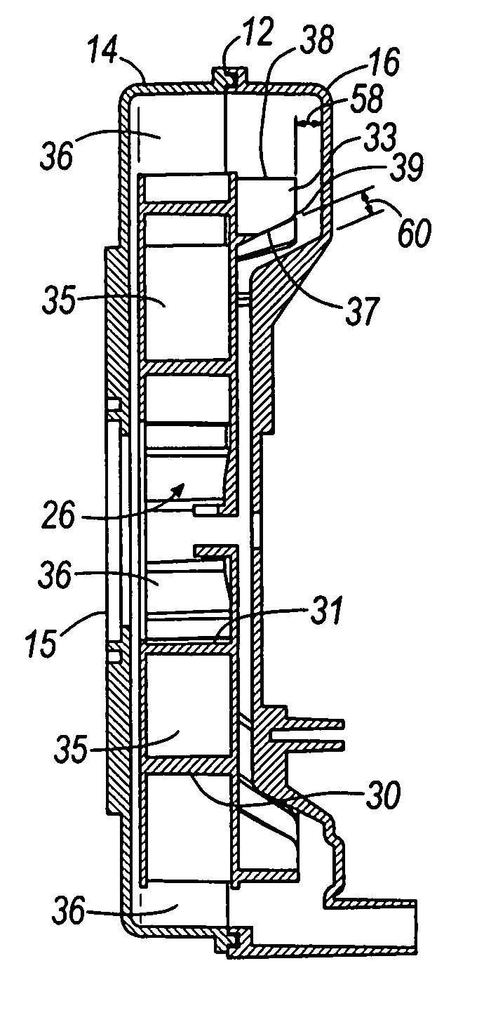
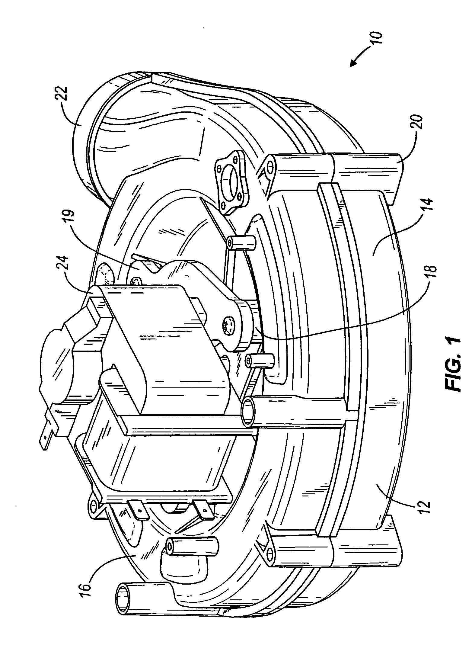
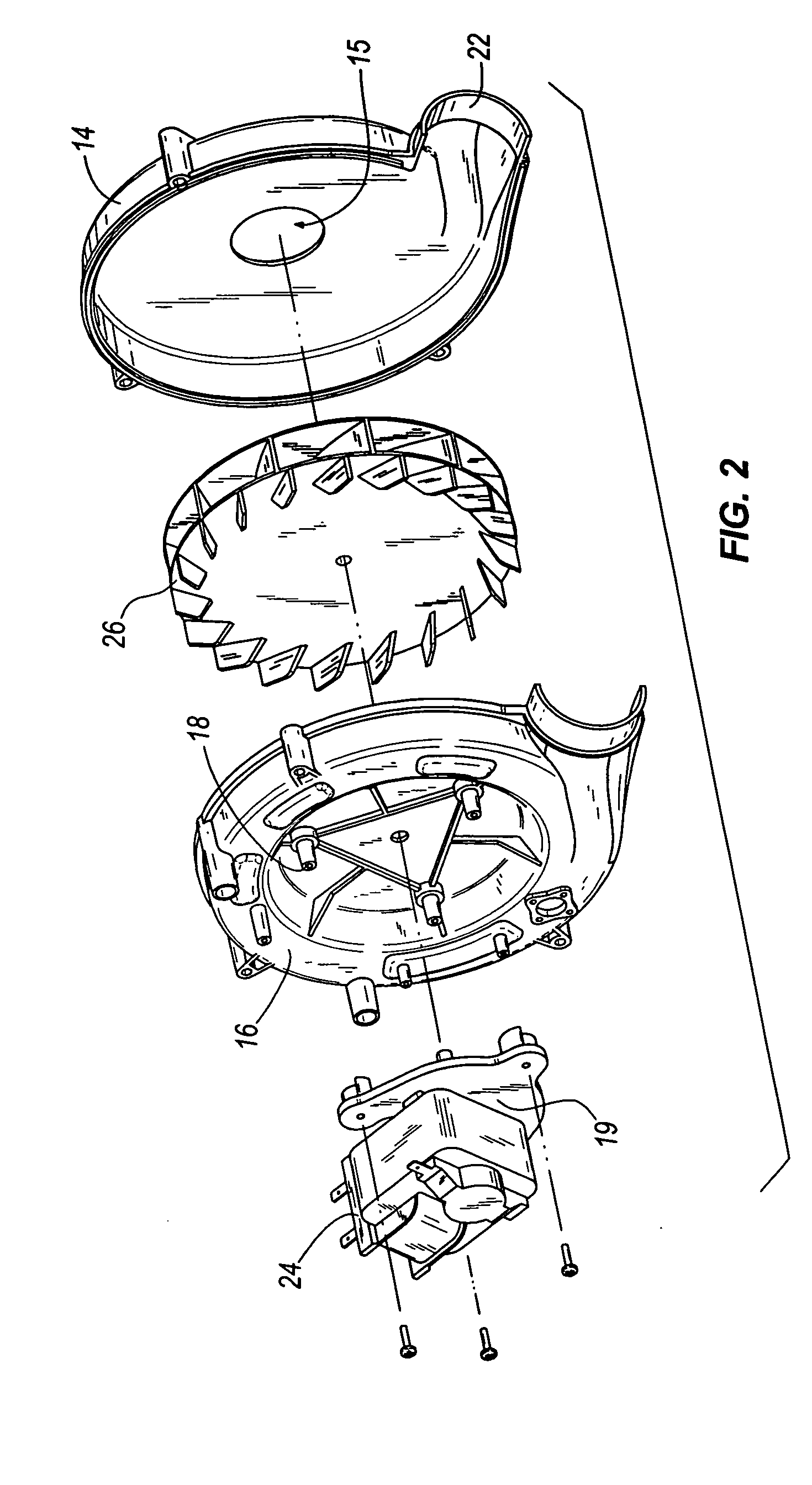
[0029] As illustrated in FIGS. 1 and 2, a fan assembly 10 according to an exemplary embodiment of the present invention comprises a housing 12 and an impeller 26 contained at least partially within the housing 12. A motor 24 can be mounted to the housing 12 and can be drivably connected to the impeller 26 in any conventional manner to rotate the impeller 26 in the housing 12. As discussed above, the housing 12 can be a substantially scroll-shaped housing forming an air passage 36 through which air flows. The housing 12 can be constructed in two or more portions 14, 16 to facilitate easy assembly. For example, as shown in FIG. 2, the housing 12 of some embodiments is formed in two portions 14, 16. The first portion 14 can contain an air inlet 15 to allow air to enter the fan 10 axially. The second portion 16 can provide a mounting surface for the motor 24. When the housing 12 is fully assembled, the impeller 26 is at least partially contained within the two portions 14, 16 of the hou...


PUM


Abstract

The present invention generally relates to a fan and in some aspects to an impeller with increased performance or efficiency. The fan according to some embodiments of the present invention has a housing, an impeller, and a motor driving the impeller. The impeller can be manufactured and/or arranged within the housing to make the fan more efficient under certain operating conditions. In some embodiments, the impeller is equipped with blades having a non-constant radius of curvature. In other embodiments, the impeller is equipped with two sets of blades, which include primary blades and secondary blades. These blades can be offset from each other to increase performance. In yet other embodiments, the space between the secondary blades and the housing can be manipulated to increase performance. Additionally, other embodiments adjust the cross-sectional shape of the flow path through the impeller to increase performance.

Description

BACKGROUND OF THE INVENTION [0001] As is well-known in the art, many types of fans employ rotatable impellers to move air and other fluids such as fumes, exhaust, or any other type of gas or gasses (for the purposes of this specification, the term air will be used as a non-limiting generic term for all fluids). The impeller moves air through a fan housing, such as a volute or a scroll-type housing and out of an outlet. In many cases, air generally enters the housing axially, travels through the impeller, and leaves the housing generally tangentially. [0002] Air pressure in various locations within a fan housing is typically important to the performance or efficiency of the fan, as is the ability of the fan to produce a pressure differential across the impeller. The pressure producing capacity of a centrifugal fan will vary depending upon certain fan characteristics such as blade depth, tip speed, and blade angle. In turn, the blade angle can be somewhat dependent upon the type of bl...

Claims


Application Information

Patent Timeline
Patent Type & Authority Applications(United States)
IPC IPC(8): F03B1/04F04D17/02F04D29/16
CPCF04D29/162F04D17/025
Inventor ZENG, LING-ZHONGSHELBY, RICHARD R.BUCKLEY, MICHAEL F.
Owner REVCOR
Why Eureka
Try Eureka