Engine driven working machine

a working machine and engine technology, applied in the direction of electric control, piston pumps, cleaning using liquids, etc., can solve the problems of waste of energy and insufficient power, and achieve the reduction of exhaust gas consumption, the reduction of engine running noise, and the effect of improving operation efficiency

Inactive Publication Date: 2005-09-01
HONDA MOTOR CO LTD
View PDF12 Cites 21 Cited by
  • Summary
  • Abstract
  • Description
  • Claims
  • Application Information

AI Technical Summary

Benefits of technology

[0007] In view of the foregoing, an object of the invention is to provide an engine driven type of working machine such as the washing machine which can save the fuel, reduce the exhaust gas, and decrease the running noise while facilitating the start and the stop of the washing operation.
[0014] According to the first aspect of the invention, the engine can be stopped in the standby state in which the fluid discharge operation by the discharge device is paused, and the engine can be started up when the fluid discharge operation is about to be performed. Therefore, the needless standby running is decreased and the effects such as a fuel economy, the decrease in running noise, and the exhaust gas reduction can be improved. The battery which supplies electric power to the starter-motor is charged by the engine driven generator, so that the invention can sufficiently respond to the case in which the start operation and the stop operation are frequently performed.
[0017] According to the fourth aspect of the invention, when the engine driven type of working machine detects that the working switch is turned off for longer time than a predetermined time and decides that the stop duration of the operation is long, the engine can be stopped. In this case, the time when the engine driven type of working machine decides whether the engine is stopped is appropriately set according to an operation mode. Therefore, the waste that the operation is paused while the engine is running can be eliminated without decreasing operation efficiency.
[0018] According to the fifth aspect of the invention, when the operator takes up the handheld discharge device, the standby switch can detect that the engine driven type of working machine is in the operation standby state, and the engine which is stopped can be started up responsive to the detection of the standby switch. Therefore, the engine driven type of working machine becomes the state in which the fluid can be discharged until the operator takes up the discharge device by hand and transfers to the next movement, so that the fluid discharge operation can substantially be started without waiting time when the operator starts the operation.
[0020] Thus, according to the invention, the decrease in running noise of the engine, the used fuel economy, and the exhaust gas reduction can substantially be realized while the operation efficiency can be improved, in the washing operation which is performed by discharging the fluid such as the washing water.

Problems solved by technology

In the control device described in the above Patent Publications, because the engine is operated at the low number of revolutions while being in a standby state, the fuel economy can be improved to a certain level, however it is not sufficient.
The high-pressure pump is still running even while the washing operation is pausing, so power supply is needed to return excess water or unloaded water back to a water tank, that causes waste of energy.
However, an operator is forced to operate to turn off a switch provided for start and stop washing and to perform stop operation of the engine besides.

Method used


Image

  • Engine driven working machine
  • Engine driven working machine
  • Engine driven working machine

Examples


Embodiment Construction

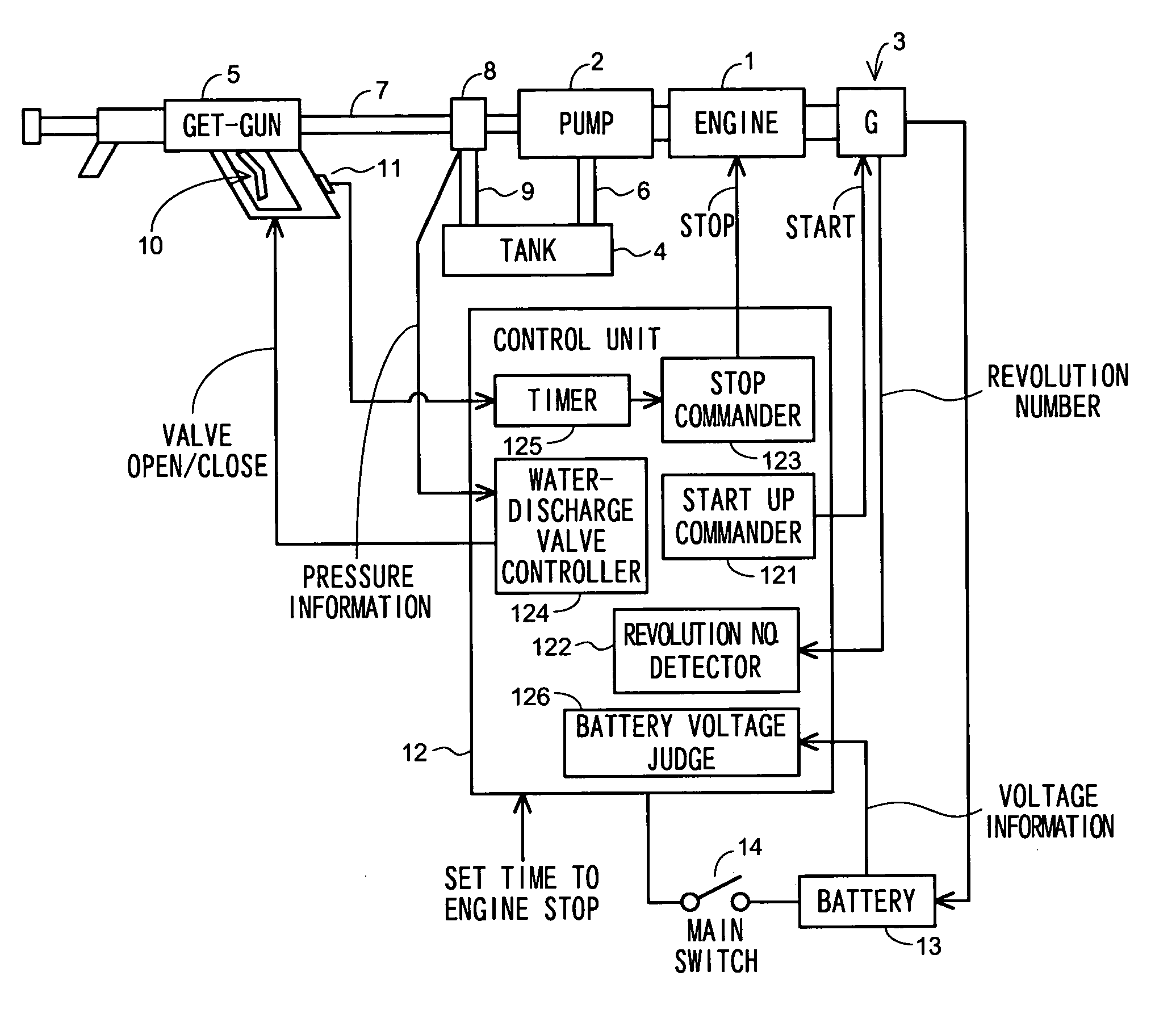
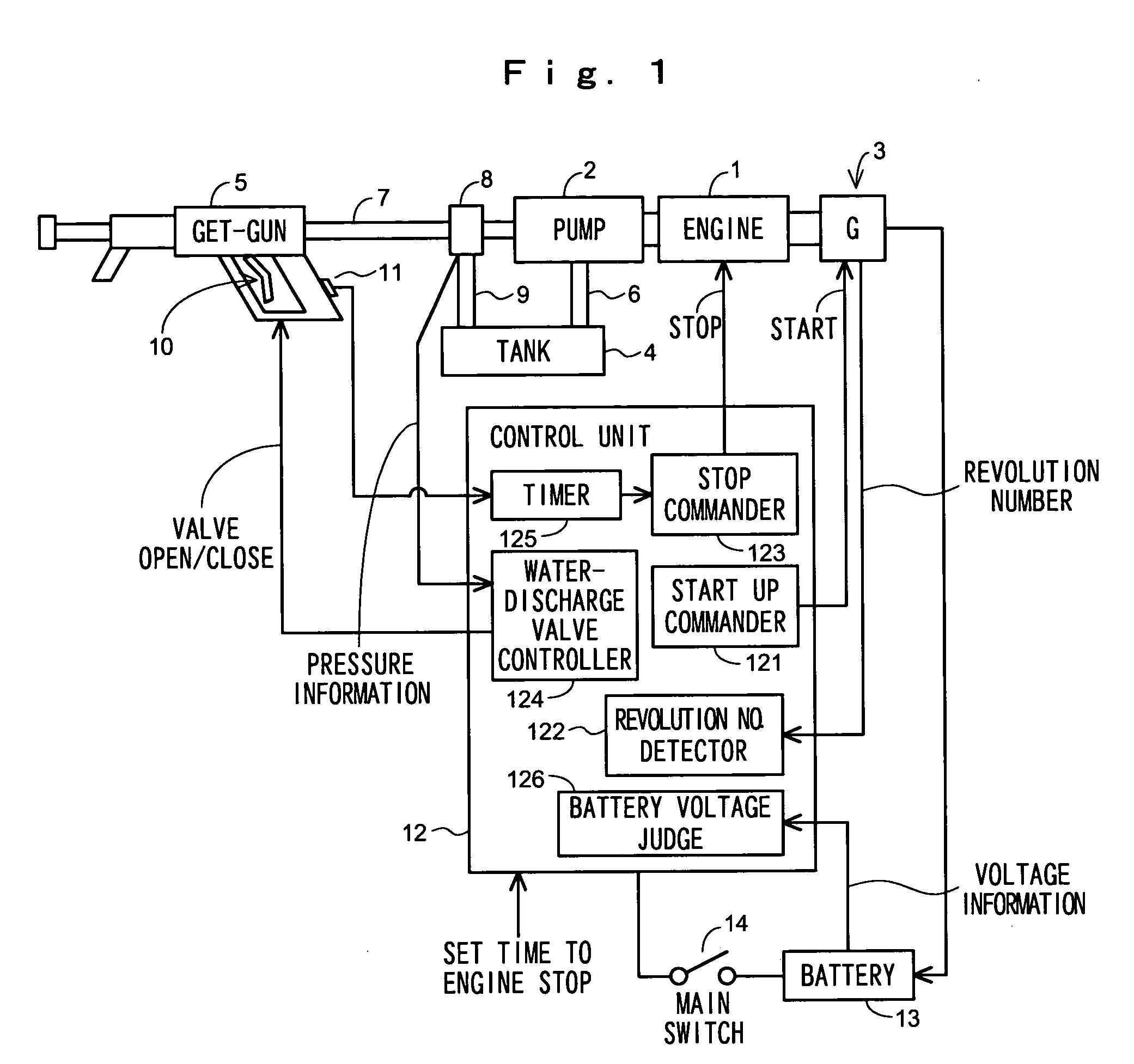
[0025] Referring now to the accompanying drawings, a preferred embodiment of the invention will be described in detail. FIG. 1 is a block diagram showing a system configuration of an engine driven type of high-pressure washing machine according to the embodiment of the invention. An engine 1 is an air-cooled four-cycle engine. One end of an output shaft is coupled to a pump 2, and the other end is coupled to a starter-motor generator 3 which is used as both a starter motor and a generator. The pump 2 pumps up the washing water stored in a tank 4 to supply the washing water to a washing-water jet gun 5. A water inlet of the pump 2 is coupled to the tank 4 through a water-supply pipe 6, and an outlet of the pump 2 is coupled to the jet gun 5 through a high-pressure hose 7. An unloader valve 8 is provided on the high-pressure hose 7. The unloader valve 8 includes a return pipe 9 and a pressure sensor (not shown). The return pipe 9 extends to the tank 4 to return the excess water to the...


PUM


Abstract

In an engine drive washing machine, a discharge switch 10 is provided in a jet gun 5. When the switch 10 is turned off, an engine 1 is stopped. When the switch 10 is turned on, the engine 1 is started up to drive a pump 2. When an outlet pressure of the pump 2 is not lower than a predetermined value, a water-discharge valve in the gun 5 is opened to cause the water to be discharged. When the switch 10 is not turned off for a long time, the engine 1 is stopped. When an operator takes up the gun 5 to start the operation, the engine 1 is started up. The engine-drive type of washing machine is provided with a battery 13 for a starter motor, and the battery 13 is charged by a generator function of a starter-motor generator 3 during the operation of the engine 1.

Description

BACKGROUND OF THE INVENTION [0001] 1. Field of the Invention [0002] The present invention relates to an engine driven type of working machine, which stops its operation while standby state to eliminate wasteful running. [0003] 2. Description of the Related Art [0004] An engine driven type of high-pressure washing machine which can discharge washing water with an engine driven pump is well known. For example, Japanese Patent Publication of examined patent application No. H5-38132 and Japanese patent Publication of examined Utility Model application No. H6-41673 disclose a control device in the engine driven type of high-pressure washing machine which can automatically decrease engine revolution speed while stopping wash operation. The control device saves fuel, reduces exhaust gas, and decreases running noise. [0005] In the control device described in the above Patent Publications, because the engine is operated at the low number of revolutions while being in a standby state, the fue...

Claims


Application Information

Patent Timeline
Patent Type & Authority Applications(United States)
IPC IPC(8): B08B3/02F02D29/00F02D29/02F02D29/04F02D29/06F02D45/00F02N11/04F02N11/08F04B49/02
CPCF04B49/02
Inventor KAWAKAMI, TOSHIAKIINAGAWA, TOSHINORIWAKITANI, TSUTOMU
Owner HONDA MOTOR CO LTD
Why Eureka
Try Eureka