Injection molding tool

a technology injection molding tool, which is applied in the field of injection molding nozzle, can solve the problems of reducing the precision of the arrangement reducing the accuracy the injection molding nozzle cannot be accurately positioned in the base body of the injection molding tool, so as to achieve high thermal resistance area, prevent leakage, and high precision

Active Publication Date: 2005-09-01
OTTO MANNER INNOVATIONS
View PDF2 Cites 4 Cited by
  • Summary
  • Abstract
  • Description
  • Claims
  • Application Information

AI Technical Summary

Benefits of technology

[0014] The first mounting element and / or the second mounting element do not need to fully surround the injection molding nozzle. Instead of being rings, they may be in the form of segments which are connected to the injection molding nozzle by dovetail joints. Still, it is advantageous if at least the second element fully surrounds the injection molding nozzle as it is provided in one embodiment of the invention. In this way, a seal can be formed to prevent leakages during the injection molding procedure. With the precise machining of the second mounting element not only can the injection molding nozzle be arranged on the base body of the injection molding body in a highly precise manner but, furthermore, a well sealed transition is formed between the injection molding nozzle and the base body.
[0015] With the injection molding tool according to the invention, injection molding nozzles can be installed into the injection molding tool with high precision, such that a high thermal resistance area is generated between the injection molding nozzle and the injection molding tool. Since the injection molding nozzles according to the invention are physically not different from injection molding nozzles without mounting elements of low heat conductivity, the injection molding nozzles according to the invention can be treated just like conventional injection molding nozzles. Furthermore, it is easily possible to replace conventional injection molding nozzles by injection molding nozzles according to the invention. As a result, conventional injection molding tools can easily be modernized by replacement of their conventional injection molding nozzles with injection molding nozzles according to the invention.

Problems solved by technology

This is disadvantageous particularly in connection with hot channel injection molding tools, since, in order to be able to manufacture an injection molding part of high quality the injection molding material is to be maintained within a hot channel nozzle at a relatively constant temperature.
This however is very expensive.
However, the placement of such a ring or washer between the injection molding nozzle and the base body reduces the precision of the arrangement of the injection molding tool.
With such a ceramic ring or, respectively, ceramic washer the injection molding nozzle can no longer be accurately positioned in the base body of the injection molding tool by means of a press fit.

Method used


Image

  • Injection molding tool
  • Injection molding tool

Examples


Embodiment Construction

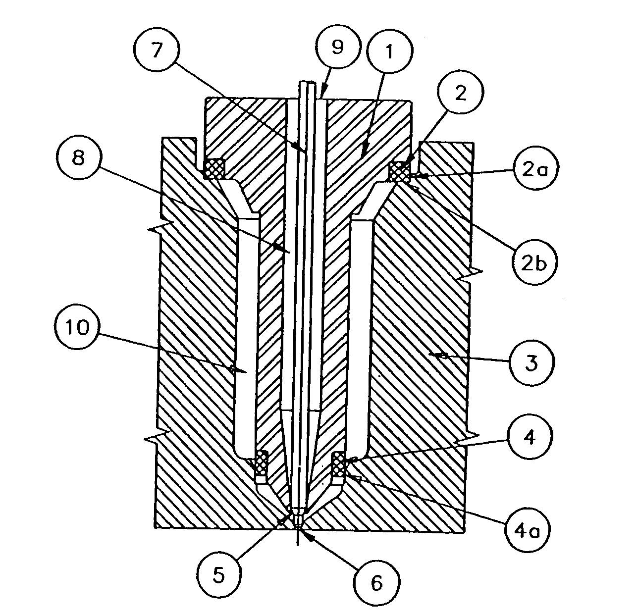
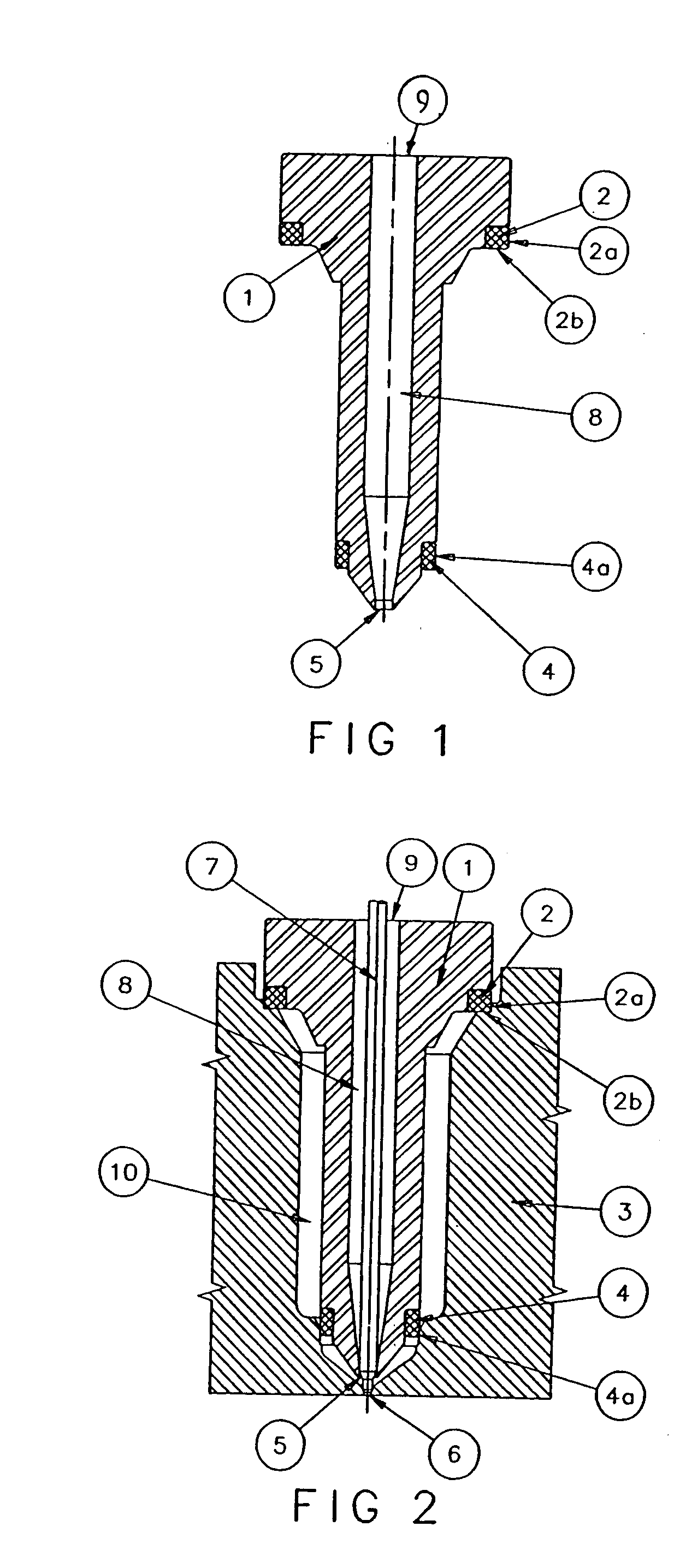
[0019] As shown in FIG. 1, an injection molding nozzle 1 includes a discharge opening 5 for the discharge of molding material. The discharge opening 5 forms the end of a supply channel 8 provided with an inlet opening 9 at the end of the injection molding nozzle opposite the discharge opening 5.

[0020] At the end opposite the discharge opening 5, the injection molding nozzle diameter is increased whereby a head similar to a bolt head is formed with a shoulder including a recessed area in which a first mounting element of low heat conductivity in the form of a first ceramic ring 2 is arranged. The ceramic ring 2 is firmly attached to the injection molding nozzle 1 by cementing.

[0021] At its end including the discharge opening 5, the injection molding nozzle 1 has a conical shape. The injection molding nozzle 1 further is provided at this end with a circumferential shoulder which forms a recess in which a ceramic ring 4 is arranged forming a second ceramic ring 4. The second ceramic ...


PUM

PropertyMeasurementUnit
heat conductivityaaaaaaaaaa
temperatureaaaaaaaaaa
processing temperatureaaaaaaaaaa

Abstract

In an injection molding nozzle for an injection molding tool having an opening for receiving the injection molding nozzle, at least a first mounting element of low heat conductivity is firmly connected to the injection molding nozzle so as to permit accurate machining of the mounting element together with the nozzle such that the nozzle can be installed in the opening of the molding tool by an accurate press fit without directly contacting the base body of the molding tool.

Description

BACKGROUND OF THE INVENTION [0001] The invention resides in an injection molding nozzle which is installed in a base member of an injection molding tool by means of a support element which has a lower heat conductivity than the base member. The invention also relates to an injection molding tool which includes such an injection molding nozzle. [0002] Such injection molding nozzles and injection molding tools are well-known in the art. [0003] In order to accommodate high quality requirements, an injection molding nozzle must be installed into the base body of an injection molding tool with high accuracy. Particularly an injection nozzle with a needle valve must be installed in the base body of the injection molding tool with high accuracy, since it is important for good operation and long operating periods of an injection molding tool, that the valve needle is inserted into the discharge opening of the injection molding nozzle in a perfectly centered way. Injection molding nozzles ar...

Claims


Application Information

Patent Timeline
Patent Type & Authority Applications(United States)
IPC IPC(8): B29C45/27
CPCB29C45/27B29C2045/2766B29C2045/2764B29C2045/2759
Inventor SPULLER, SWENSELAK, VINCENC
Owner OTTO MANNER INNOVATIONS
Why Eureka
Try Eureka