

Cam shaft intake angle examining device
- Summary
- Abstract
- Description
- Claims
- Application Information
AI Technical Summary
Benefits of technology
Problems solved by technology
Method used
Image

Examples
Embodiment Construction
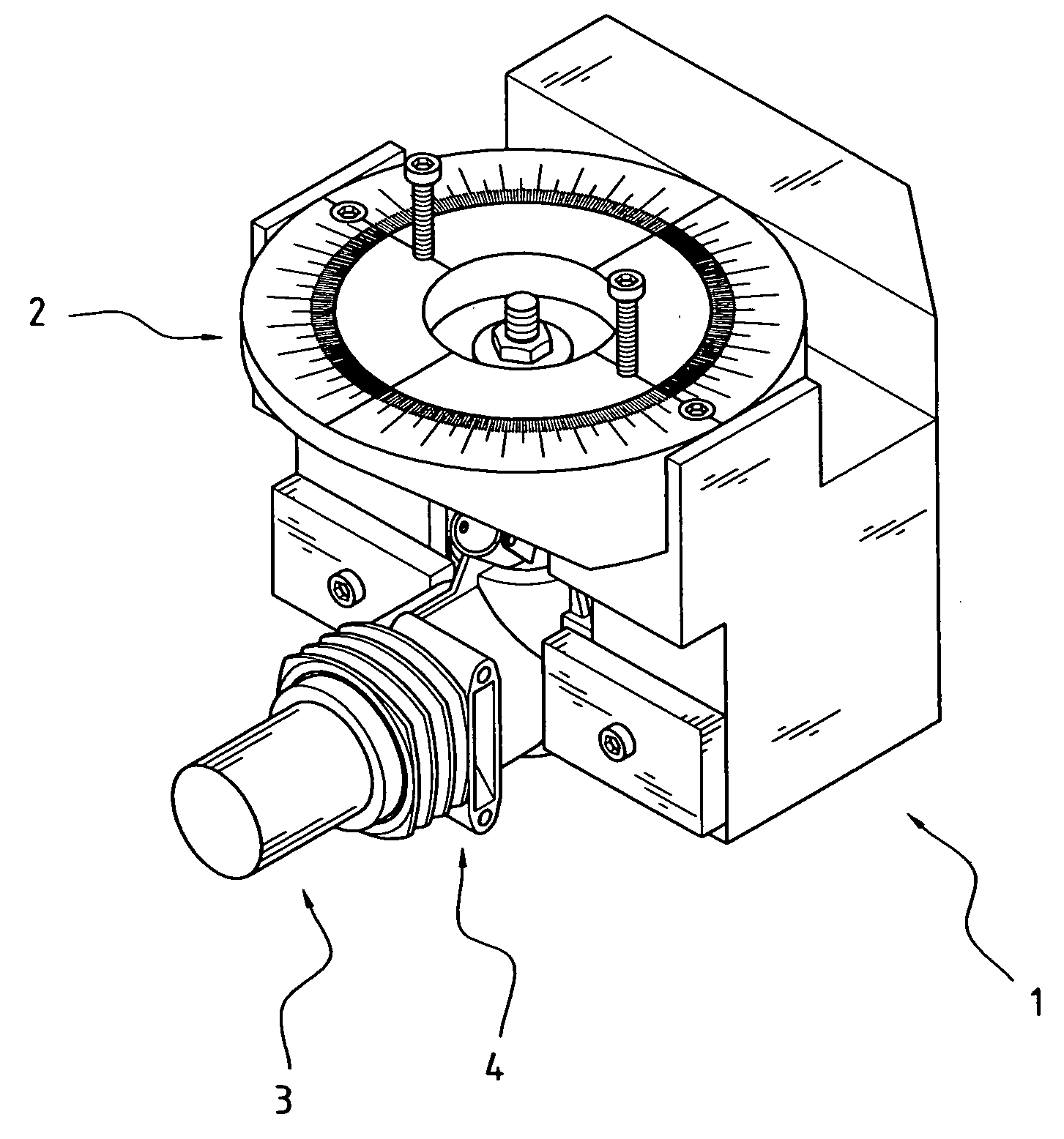
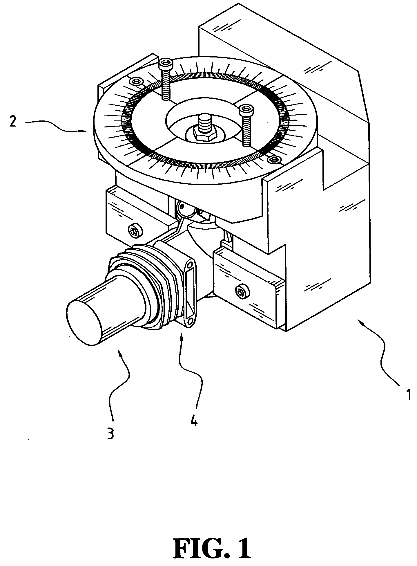
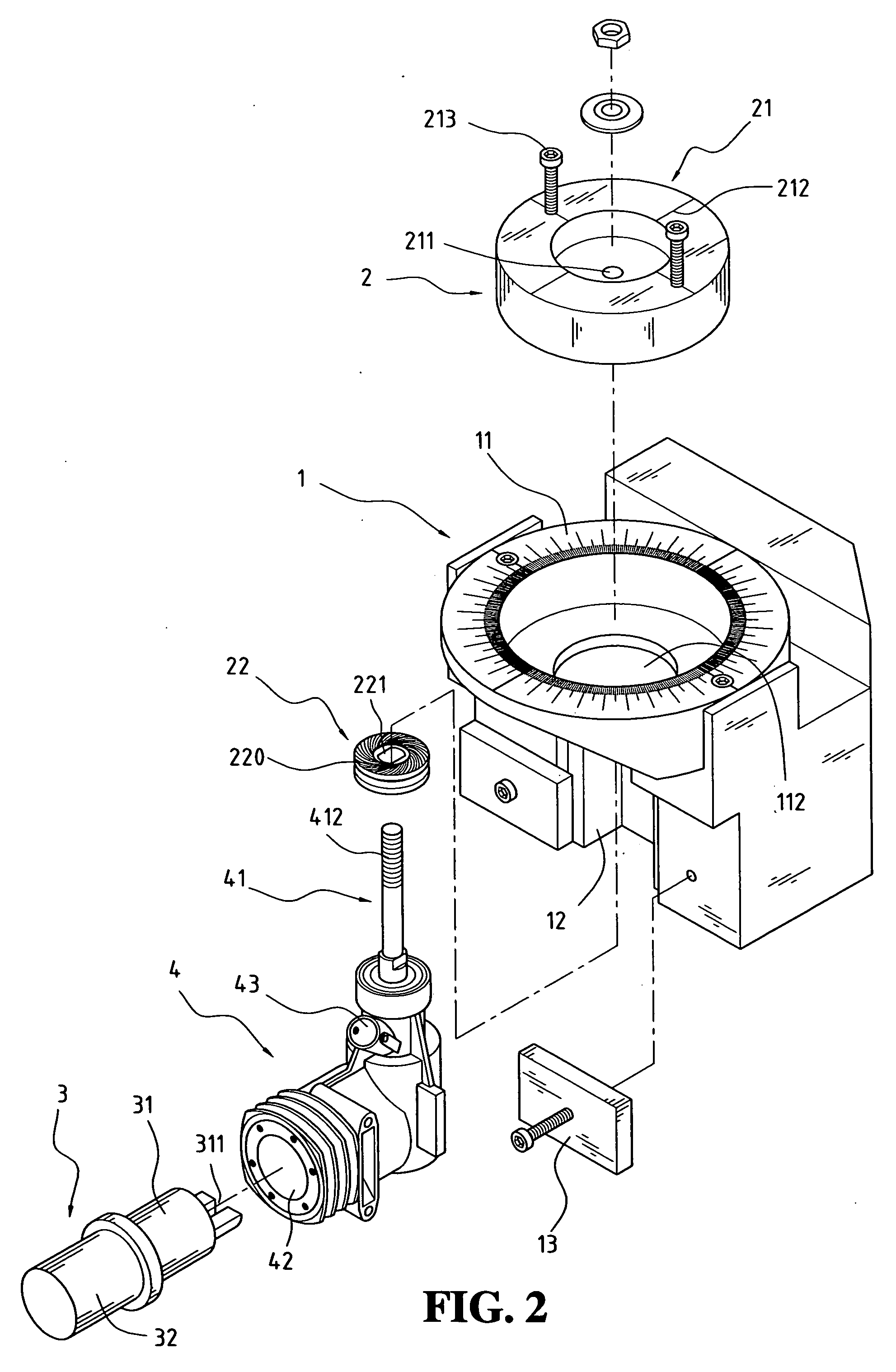
[0016] With reference to FIGS. 1 and 2, a cam shaft intake angle examining device in accordance with the present invention includes a base 1, a measuring disk 2, and an adjusting rod 3. The engine 4 with a cam shaft 41 to be tested is a two-stroke diesel engine. The engine 4 is first secured in the base 1. The adjusting rod 3 is used to position the cam shaft 41 at an initial position (0 point). A connecting block 22 is placed on the cam shaft 41. A rotation disk 21 is measured and fixed on the connecting block 22. After the adjusting rod 3 is taken away from the base 1, the engine 4 is ready for test.
[0017] The base 1 is defined with a fixing recess 12. The fixing recess 12 is so defined that it is adapted to mate with the shape of the cam shaft 41. The base 1 further has a ring 11 with scales that has a prevision of 0.1 degrees. A fixing hole 111 is defined in the ring 11 and a connecting hole 112 is defined in a bottom defining the fixing hole 111 to communicate with the connect...
PUM
 Abstract
Description
Claims
Application Information