Method and system of determining life of turbocharger

a turbocharger and life measurement technology, applied in the field of rotational compressors, can solve the problems of limiting the stress on the turbocharger, and limited life of the turbocharger

Active Publication Date: 2005-09-08
CATEPILLAR INC PATENT DEPT
View PDF7 Cites 53 Cited by
  • Summary
  • Abstract
  • Description
  • Claims
  • Application Information

AI Technical Summary

Problems solved by technology

Engineers have long known that turbochargers are subjected to stresses that limit the life of the turbocharger.
Specifically, the life of a turbocharger is limited by both low cycle fatigue and creep on a compressor wheel and a turbine wheel of the turbocharger.
Low cycle fatigue results from acceleration of the turbocharger during load changes.
However, when the turbocharger rotational speed decreases, the same material may contract.
The repeated expansion and contraction of the material comprising the compressor and turbine wheel rotors will cause fatigue, which may eventually lead to turbocharger failure.
Further, the life of a turbocharger is limited by creep.
Although the turbine wheel and compressor wheel may be comprised of different materials and operate at different temperatures, creep can eventually cause both the compressor and turbine wheels to fail.
The material properties can deteriorate due to the metallurgical changes, such as oxidation or corrosion, when subjected to high temperatures for a period of time.
Although the turbine wheel and the compressor wheel may be comprised of different materials and operate at different temperatures, material degradation can contribute to failure caused by fatigue and creep in both the compressor and turbine wheels.
Further, turbochargers that have similar applications may also be exposed to different turbocharger operating conditions depending on the duty cycle of the turbocharger.
Because fatigue and creep will eventually cause the turbocharger to fail, the turbocharger must be replaced or serviced prior to failure.
However, because turbochargers have many different applications, using a representative duty cycle to predict the lives of various turbochargers leads to over estimation of some turbochargers' lives and under estimation of other turbochargers' lives.
If the representative duty cycle over estimates the life of the turbocharger, the turbocharger will fail prior to being replaced, resulting in costly repairs and customer inconvenience.
If the representative duty cycle under estimates the life of the turbocharger, the turbocharger will be unnecessarily replaced, resulting in unnecessary expense and inconvenience.
Although the method of monitoring the actual operating condition reduces the over estimation and under estimation concerns, there are additional costs involved with direct monitoring of the turbocharger operating condition.
For instance, there are costs associated with the assembly and installation of turbocharger rotational speed sensors and connections between the computer processor and the sensors.
Moreover, the LaRue fatigue life monitor only monitors an estimated fatigue life of the turbine and compressor wheel, and does not monitor the creep life of the wheels.
Depending on the duty cycle of the turbocharger, the turbocharger life may be limited by creep rather than by fatigue.
Similarly, the LaRue fatigue life monitor does not consider the effect of possible material degradation when determining the fatigue life of the turbine and compressor wheels.

Method used


Image

  • Method and system of determining life of turbocharger
  • Method and system of determining life of turbocharger
  • Method and system of determining life of turbocharger

Examples


Embodiment Construction

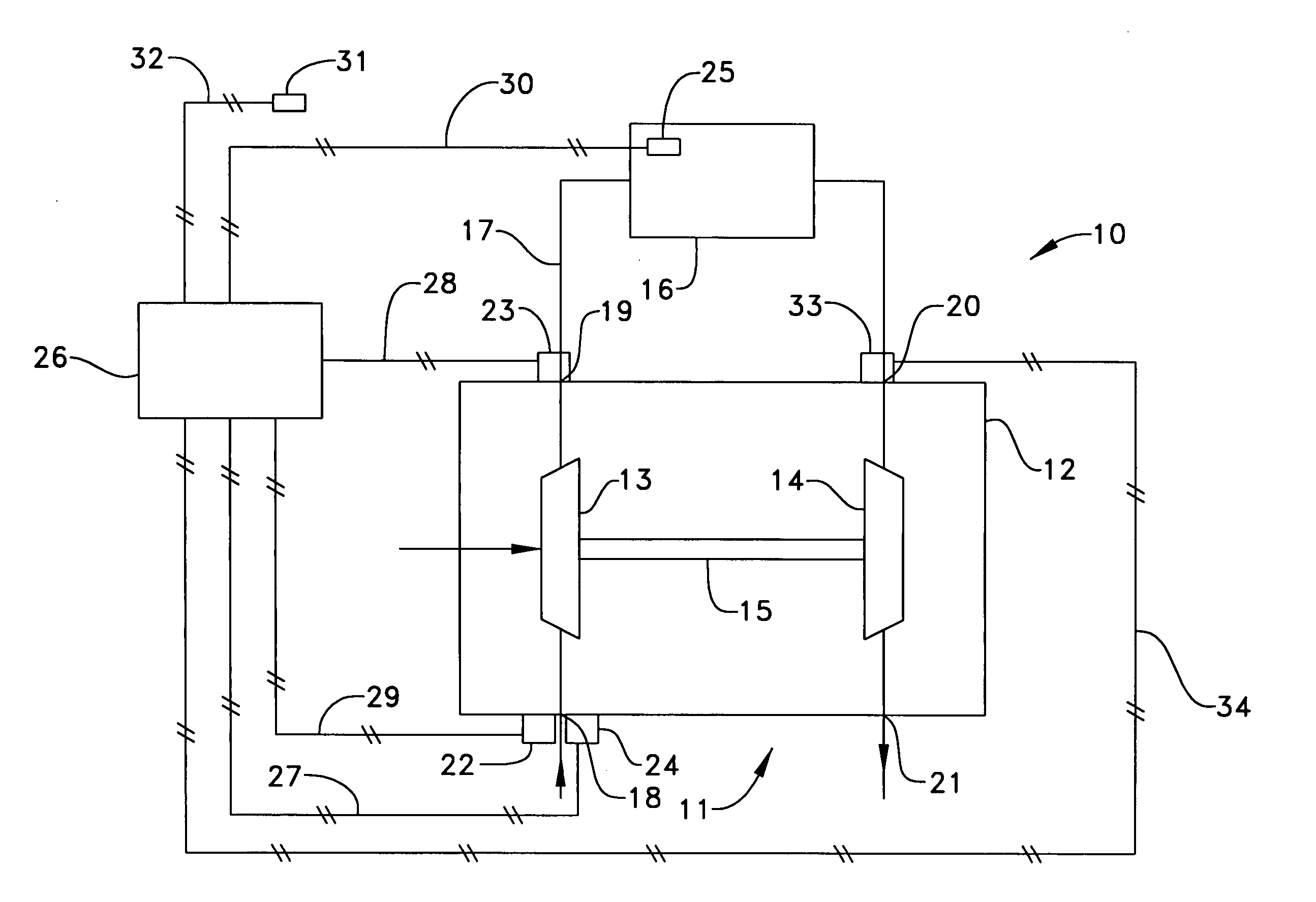
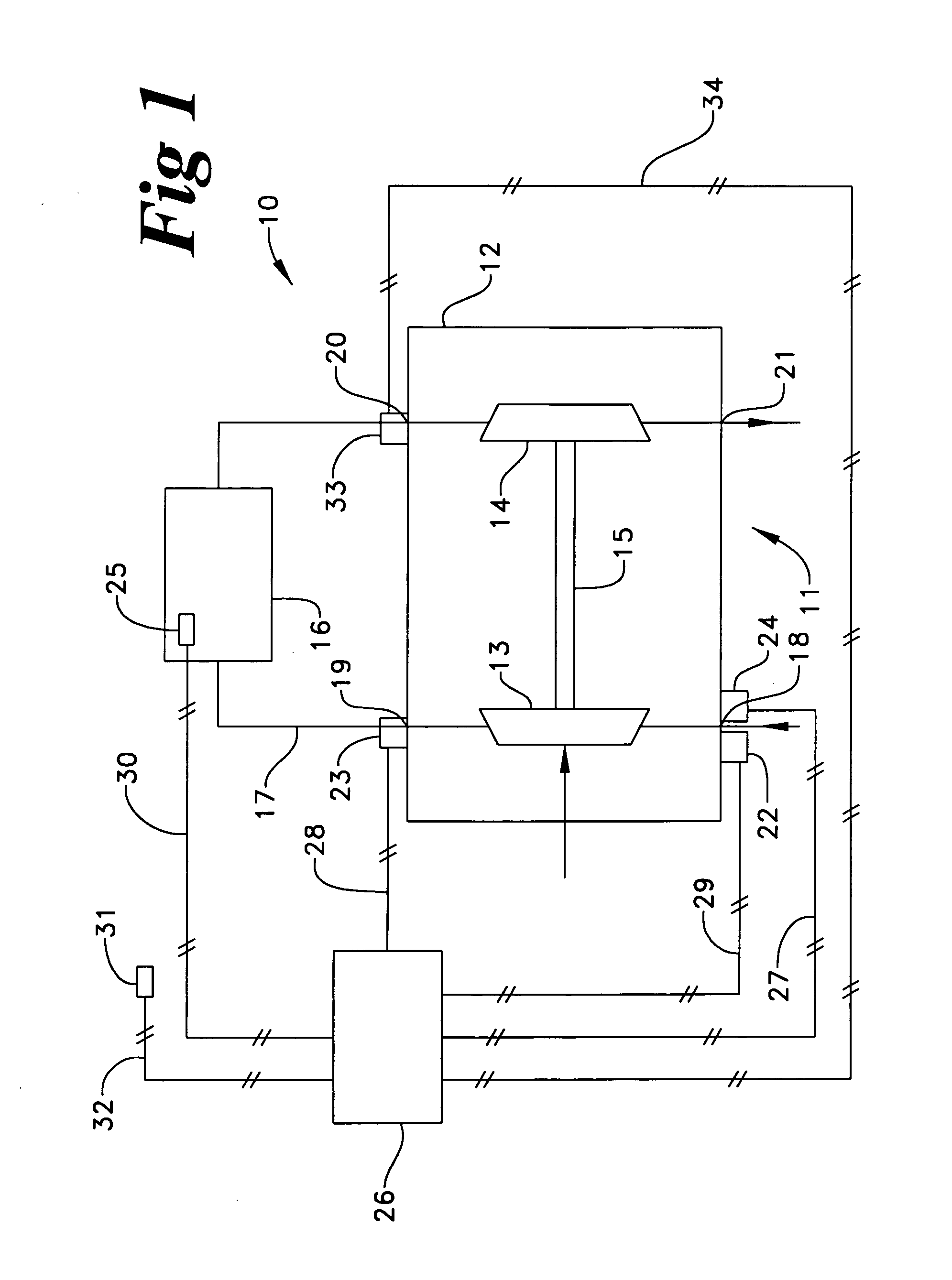
[0017] Referring to FIG. 1, there is shown a schematic representation of a turbocharger life determining system, according to the present invention. The turbocharger life determining system 10 includes a turbocharger 11 mounted within a turbocharger housing 12. The turbocharger 11 includes a compressor wheel 13 and a turbine wheel 14 connected by a shaft 15 in a conventional manner. Air is circulated through the turbocharger 11 and an engine 16 via an air line 17. The turbocharger housing 12 defines a compressor inlet 18, a compressor outlet 19, a turbine inlet 20, and a turbine outlet 21. A compressor inlet pressure sensor 22 is illustrated as attached to the housing 12, although the compressor inlet pressure sensor 22 could be positioned at various points within the inlet air line upstream from the compressor inlet 18. Although the compressor outlet pressure sensor 23 is illustrated as attached to the turbocharger housing 12, it should be appreciated that the compressor outlet pre...


PUM


Abstract

In order to accurately determine a life of a turbocharger, the specific use, herein referred to as a “duty cycle” of the turbocharger, should be monitored. However, in order to directly monitor the duty cycle of the turbocharger, there are additional costs of assembly and installation of a turbocharger rotational speed sensor. The present invention determines a life of a turbocharger by indirectly monitoring the duty cycle of the turbocharger through sensors that generally serve a pre-existing purpose within a vehicle or machine. A compressor inlet pressure sensor and compressor outlet pressure sensor are in communication with an electronic control module that includes a life determining algorithm. The life determining algorithm determines the life of the turbocharger based on a relationship between a sensed compressor inlet pressure and a sensed compressor outlet pressure. By monitoring the relationship between the sensed compressor inlet pressure and the sensed compressor outlet temperature, the fatigue and the creep of at least one component of the turbocharger is monitored.

Description

TECHNICAL FIELD [0001] The present invention relates generally to rotational compressors, and more particularly to a method and a system of determining a life of a turbocharger. BACKGROUND [0002] Engineers have long known that turbochargers are subjected to stresses that limit the life of the turbocharger. Specifically, the life of a turbocharger is limited by both low cycle fatigue and creep on a compressor wheel and a turbine wheel of the turbocharger. Low cycle fatigue results from acceleration of the turbocharger during load changes. When the turbocharger rotational speed increases, the centrifugal forces acting on material comprising rotors of the turbocharger compressor wheel and turbocharger turbine wheel may cause the material to expand. However, when the turbocharger rotational speed decreases, the same material may contract. The repeated expansion and contraction of the material comprising the compressor and turbine wheel rotors will cause fatigue, which may eventually lea...

Claims


Application Information

Patent Timeline
Patent Type & Authority Applications(United States)
IPC IPC(8): G01M99/00F01D25/00F02B39/16G01M15/00
CPCF01D21/003Y02T10/144F02D41/0007F02D41/221F02D2200/0406F05D2220/40F05D2260/80F05D2270/11F05D2270/3011F05D2270/3013F05D2270/304G01M15/09G07C3/08Y02T10/40F02B39/16Y02T10/12
Inventor GLADDEN, JOHN R.
Owner CATEPILLAR INC PATENT DEPT
Why Eureka
Try Eureka