Rackable composite shipping pallet for transporting and storing loads

a composite and shipping pallet technology, applied in the field of shipping pallets, can solve the problems of heavy wood pallets, high cost, and affecting the performance of conventional shipping pallets, and achieve the effects of reducing the cost of wood pallets

Inactive Publication Date: 2005-09-08
HERRING CONRAD C +1
View PDF50 Cites 15 Cited by
  • Summary
  • Abstract
  • Description
  • Claims
  • Application Information

AI Technical Summary

Benefits of technology

[0021] The deck may comprise structural fill that extends from and between the legs of at least some adjacent domes and provides continuity and additional structure to the load bearing deck. Circular hoops may be provided where the domes end at the lower surface of the load bearing deck. Webbing may be provided between the circular hoops on the lower surface of the deck to provide continuity and structure to the lower surface of the deck.

Problems solved by technology

Conventional shipping pallets are usually constructed of wood or wood products with numerous associated problems.
Wood pallets are heavy, expensive (especially those designed for four-way entry for a forklift) and subject to insect infestation.
Some shipping pallets are constructed from alternative materials, but no matter what construction material is used, conventional shipping pallets suffer from one or more significant problems: limited strength, especially over extended periods of time, cumbersome weight, flexibility and bendability, high expense, limited usability, complex production requirements, ecological unacceptability, and inability to reuse or recycle.

Method used


Image

  • Rackable composite shipping pallet for transporting and storing loads
  • Rackable composite shipping pallet for transporting and storing loads
  • Rackable composite shipping pallet for transporting and storing loads

Examples


Embodiment Construction

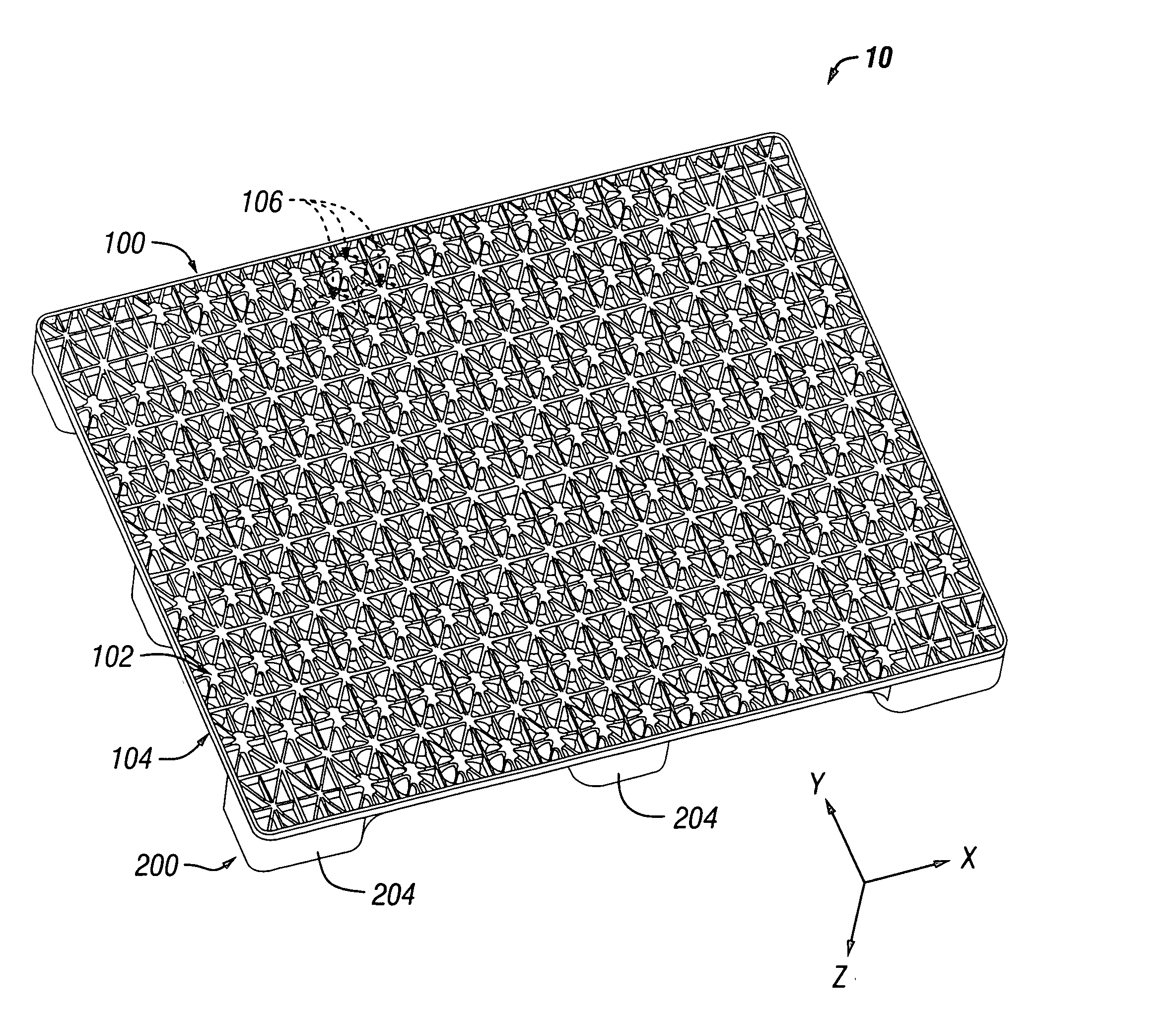
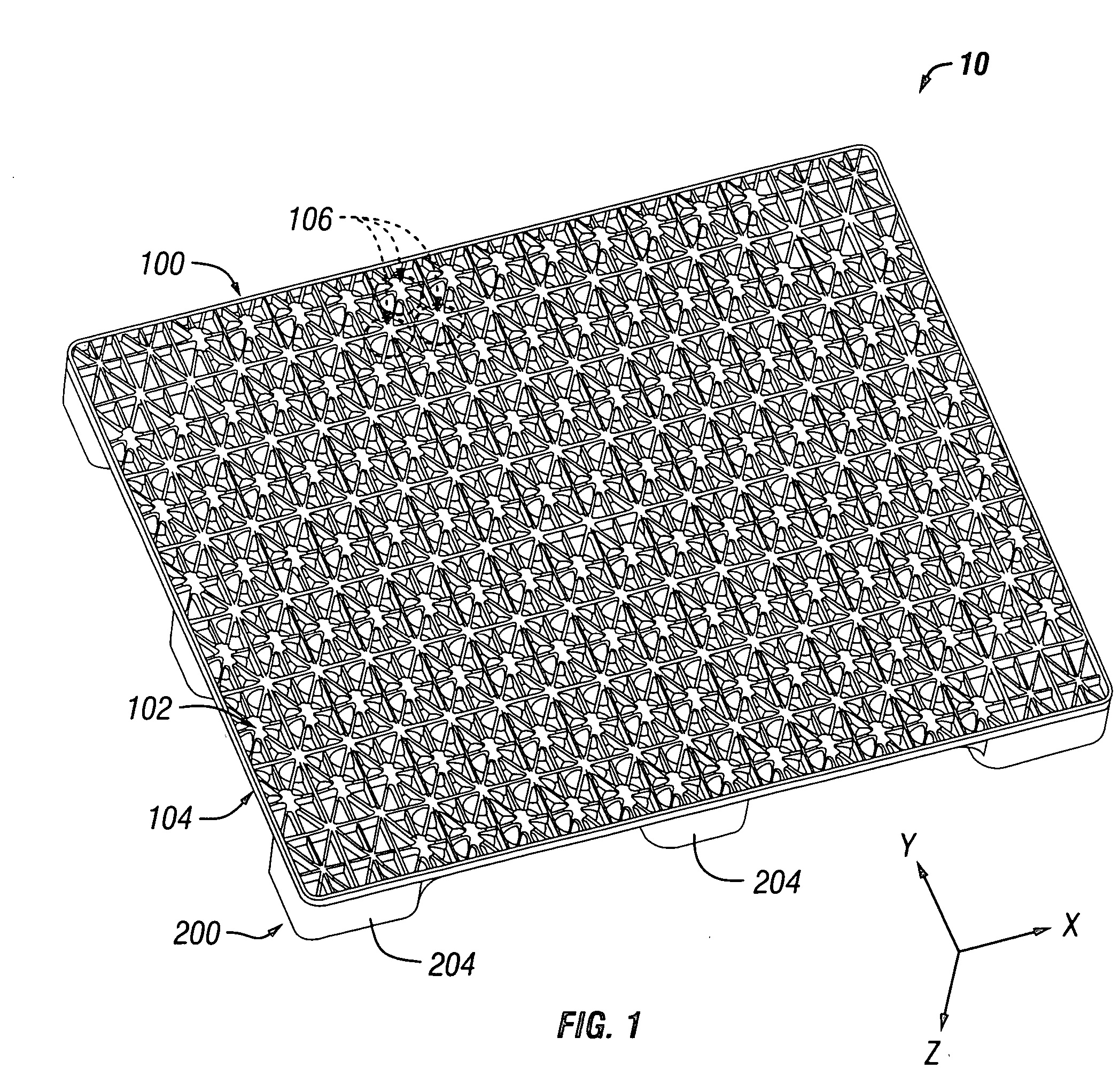
[0048] This invention is described in the following description with reference to the figures, in which like numbers represent the same or similar elements.

GLOSSARY OF TERMS AND ACRONYMS

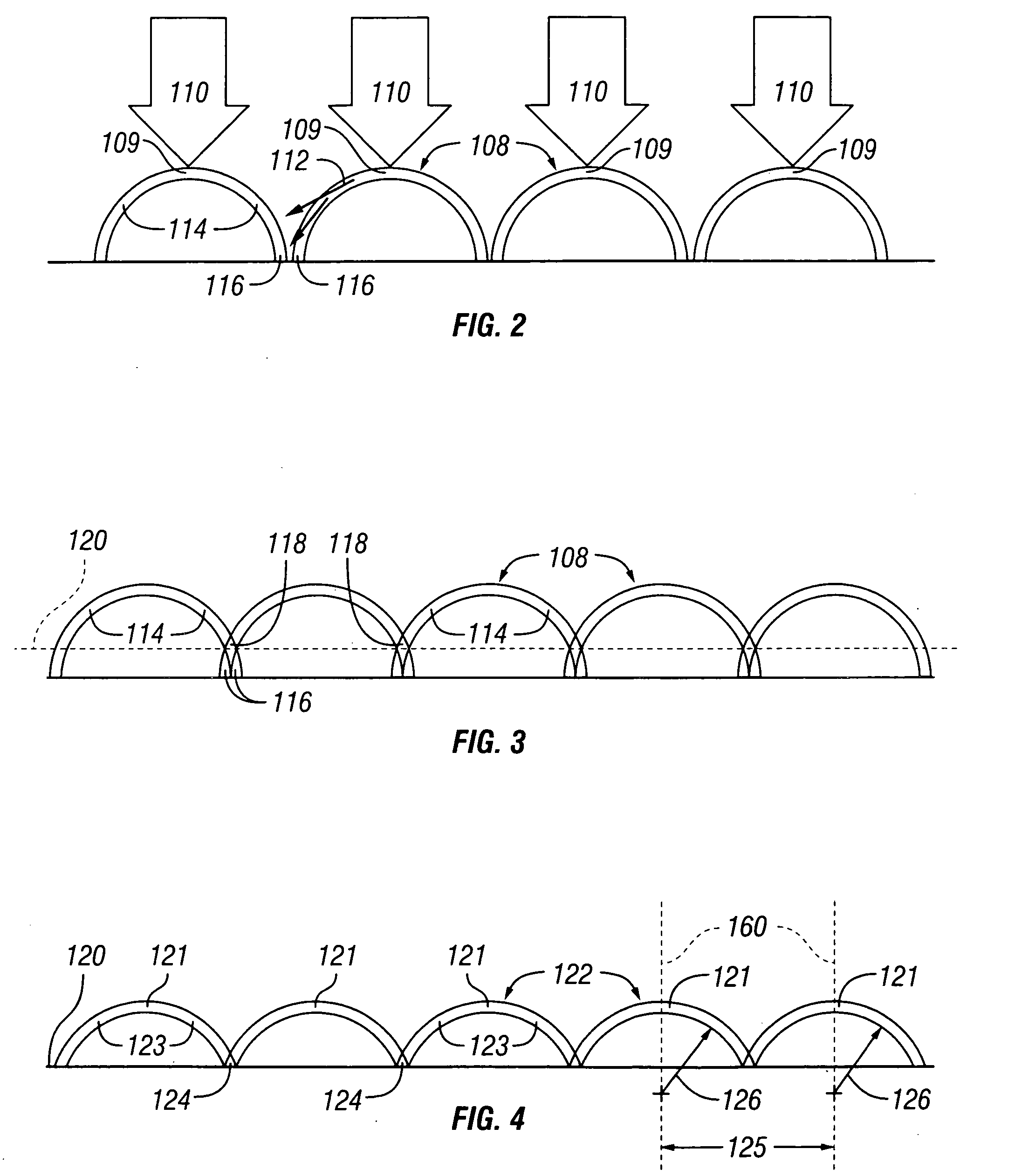
[0049] The following terms are used throughout the detailed description: [0050] arch A structure that begins at an apex has two legs that extend downwardly from the apex toward their lower ends. An arch transmits an applied load in two directions substantially laterally through the legs of the arch. A “full” arch extends fully from the apex through to a point wherein both legs are substantially vertically oriented at their lower ends. A “partial” arch has legs that have been truncated short of a full arch, such that the legs are non-vertically oriented at their lower ends. [0051] arch row A row comprising a plurality of arches. [0052] dome A three-dimensional element defined by a plurality of arches angularly arranged at varying degrees about a vertical axis extending through the apex of the arches...


PUM


Abstract

A rackable pallet is disclosed that has a load bearing deck, a plurality of cross beams, and a plurality of removable base supports connected approximately perpendicular to the cross beams, and is made of a polymer. One disclosed pallet is open from the bottom and particularly suited for use in large automated warehouses, where machinery lifts and moves pallets by remote control. In one embodiment the pallet comprises a support structure that comprises a plurality of cross beams and a plurality of base supports connected to the cross beams. The deck and the cross beams typically define a single, injection-molded piece of polymer material. The base supports may be removable for repair or replacement. In one embodiment the load bearing deck has a plurality of domes in an array that provide high strength, stiffness, and rigidity.

Description

CROSS-REFERENCE TO RELATED APPLICATION [0001] This is a continuation-in-part of application Ser. No. 10 / 364,867, filed Feb. 10, 2003, entitled LOAD BEARING STRUCTURE FOR SHIPPING PALLET, now U.S. Pat. No. 6,857,377 issued Feb. 22, 2005, which is a continuation-in-part of application Ser. No. 09 / 978,861, filed Oct. 16, 2001 entitled LOAD BEARING STRUCTURE FOR SHIPPING PALLET, both of which are incorporated by reference herein in their entirety.BACKGROUND OF THE INVENTION [0002] 1. Field of the Invention [0003] The present invention generally relates to shipping pallets. More specifically, the invention is directed toward a pallet comprising a load bearing deck and an undercarriage for receiving a forklift, palletjack, hand truck or other automated machinery. [0004] 2. Description of Related Art [0005] Pallets are widely used today to efficiently transport nearly everything worldwide, such as food, beverage, and most every manufactured item or goods. Generally shipping pallets are por...

Claims


Application Information

Patent Timeline
Patent Type & Authority Applications(United States)
IPC IPC(8): B65D19/00E04C2/296E04C2/34
CPCB65D19/0018E04C2002/3411B65D2519/00024B65D2519/00034B65D2519/00039B65D2519/00059B65D2519/00069B65D2519/00074B65D2519/00268B65D2519/00273B65D2519/00288B65D2519/00318B65D2519/00323B65D2519/00333B65D2519/00338B65D2519/00373B65D2519/00407B65D2519/00412B65D2519/00557B65D2519/00562B65D2519/00567E04C2/296E04C2/3405B65D19/0051
Inventor HERRING, CONRAD C.REYHAN, FREDRICK B.
Owner HERRING CONRAD C
Why Eureka
Try Eureka