Waterproof structure of junction box

a junction box and waterproof technology, applied in the direction of electrical apparatus casings/cabinets/drawers, coupling device connections, casings/cabinets/drawers details, etc., can solve the problems of affecting the performance of the electric parts in the junction box, the waterproofness of the cover is disadvantageous, and the junction box is prone to erosion. , to prevent the invasion of splashing water, prevent the box from being overheated, and keep the correct performance of the electric parts

Active Publication Date: 2005-09-08
YAZAKI CORP
View PDF12 Cites 40 Cited by
  • Summary
  • Abstract
  • Description
  • Claims
  • Application Information

AI Technical Summary

Benefits of technology

[0015] For achieving the object, a basic aspect of the invention is a waterproof housing of a junction box, wherein the housing is provided with at least one vent piece penetrating through a wall of the housing for ventilation of the junction box, and the vent piece has an inner wall formed with a baffle projection to prevent invasion of a splashing water.
[0016] This configuration allows that heat generated from electrical parts accommodated in the box such as relays and fuses is transferred through the vent piece, preventing a high temperature in the box to keep correct performances of the electric parts. At the same time, a splashing water entering a vehicle engine room through a clearance of a body of the vehicle hits the baffle projection not to enter the box. This prevents corrosion and electrical leak of the electrical parts. Note that the splashing water is brought during jetting water washing of the vehicle or during running of the vehicle on a rainy day. The splashing water hits a wall of a tire recess or a side panel of the vehicle to reach the junction box. This further improves heat transfer and waterproofness of the box.
[0017] Preferably, the waterproof housing is provided with a plurality of

Problems solved by technology

However, a completely closed housing is not preferable, since a drainage caused by a temperature difference between the inside and the outside of the box can not be discharged from the box to have an adverse effect on electrical parts in the box.
However, the conventional junction boxes discussed above have problems described below.
A larger opening of the drain hole 42 will serve to transfer heat but is disadvantageous for wa

Method used


Image

  • Waterproof structure of junction box
  • Waterproof structure of junction box
  • Waterproof structure of junction box

Examples


Embodiment Construction

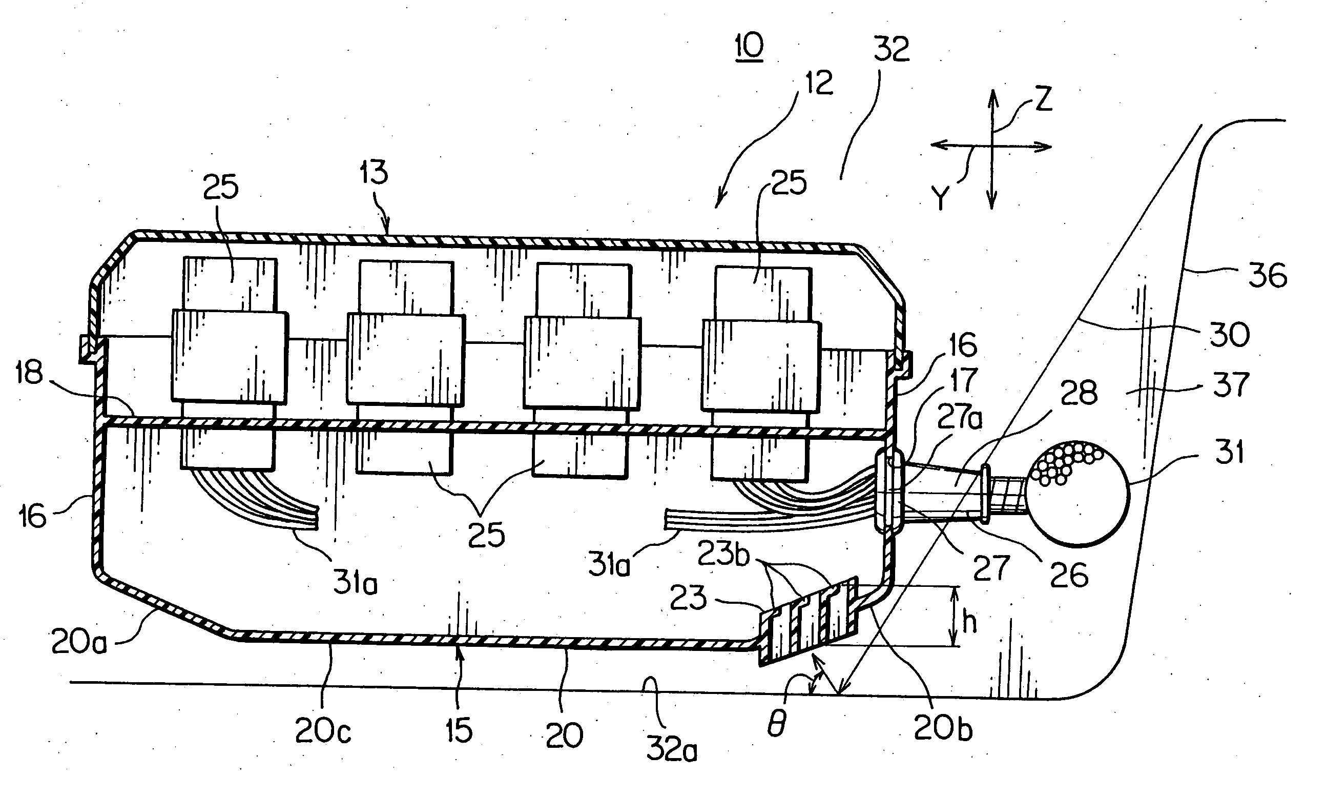
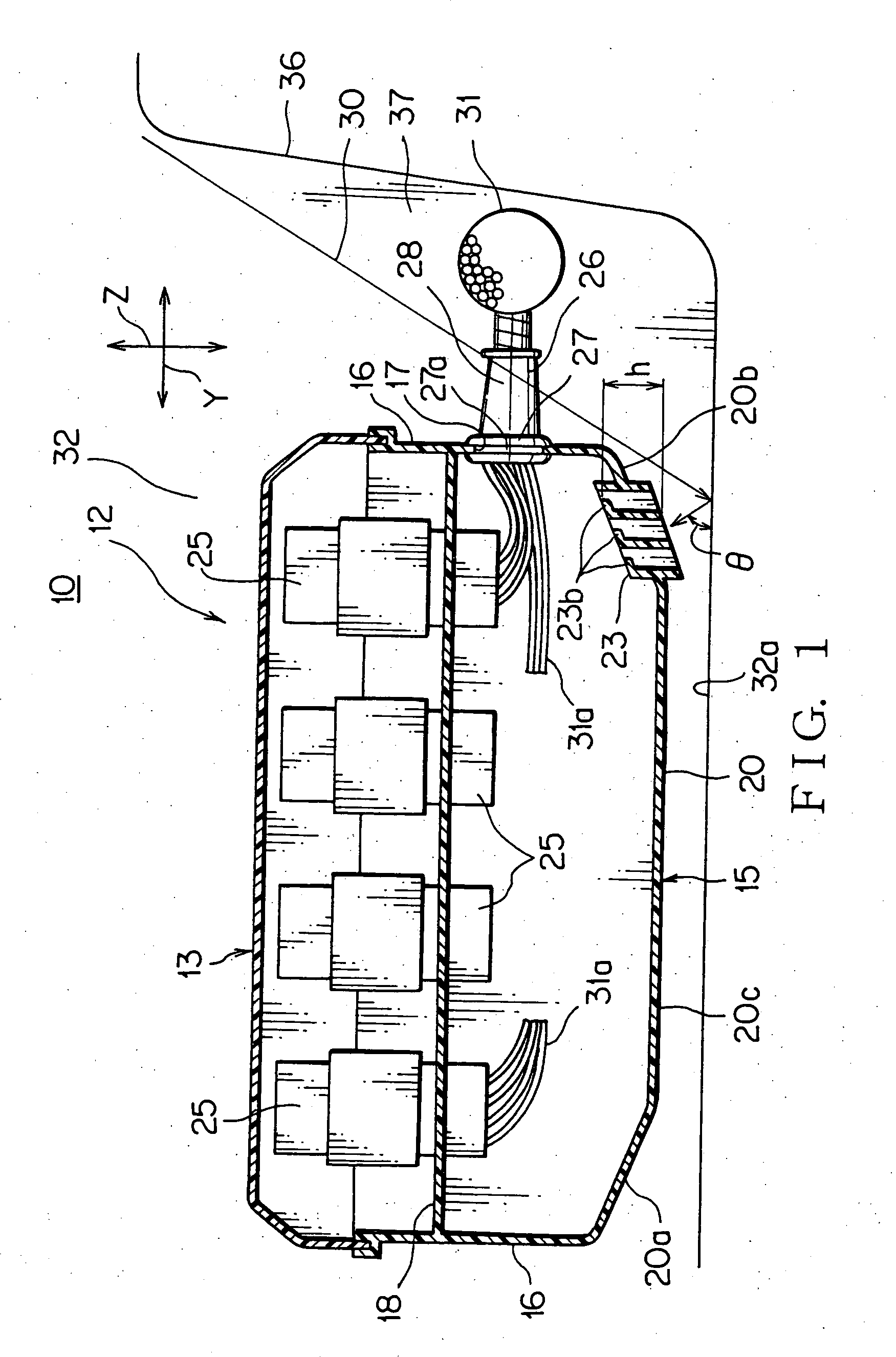
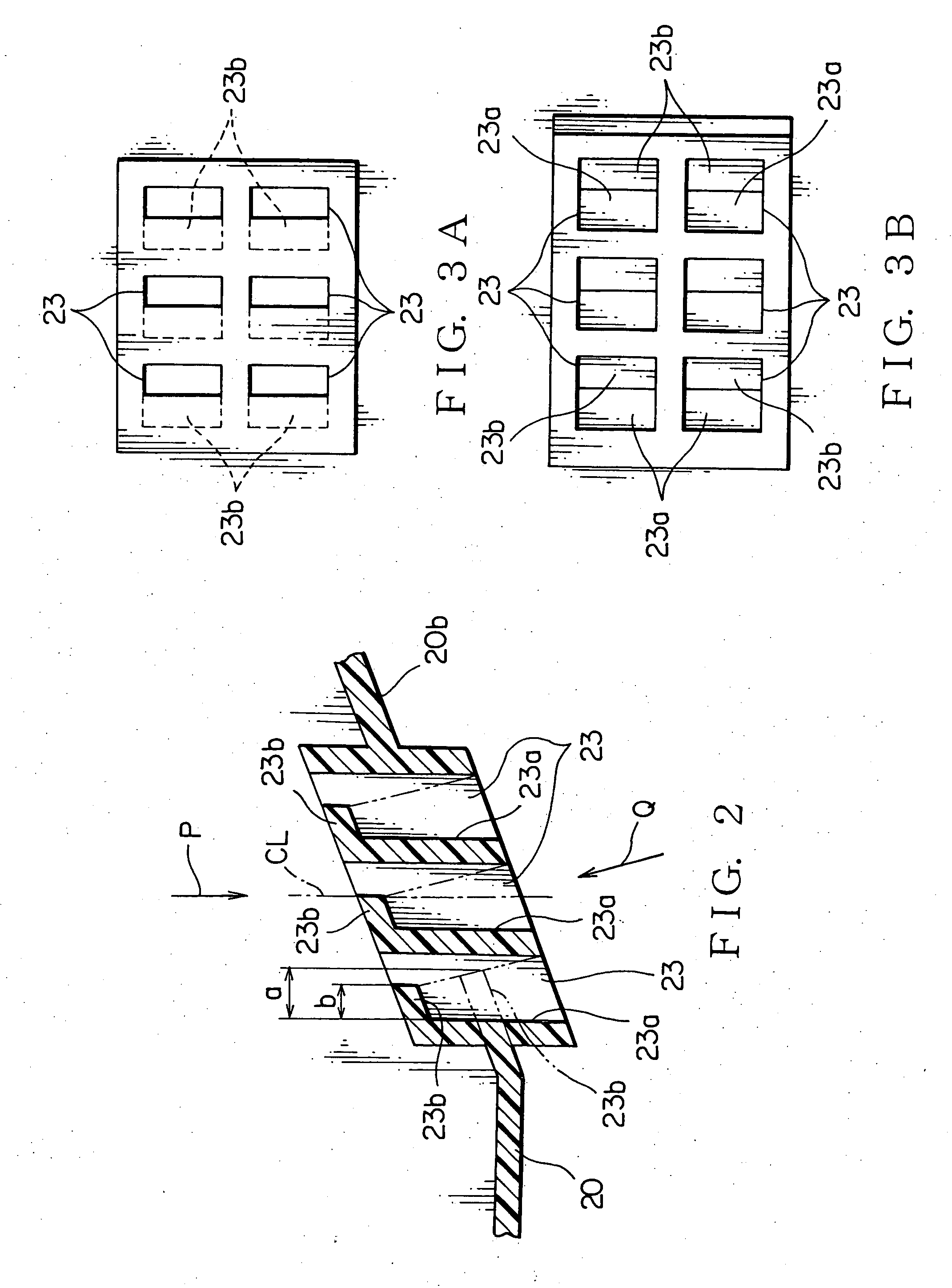
[0027] Referring to the accompanied drawings, an embodiment of the present invention will be discussed in detail. FIGS. 1 to 4 show an embodiment of a junction box according to the present invention.

[0028] The junction box is also called as a relay box or a fuse box. The junction box has a housing accomodating electric parts such as relays, fuses, and connectors. The housing also receives circuit conductors including busbars, electronic units, etc. In an automotive vehicle, the junction box is positioned between a battery and electrical equipment for power supply to the equipment and for controlling the equipment including actuators and instruments. In the embodiment, the junction box mainly includes relays, which does not intend to limit the present invention. The junction box associated with the present invention may accommodate other electrical parts.

[0029] A relay box may be disposed in a vehicle cabin, but the present invention relates to a relay box 10 disposed in a vehicle ...


PUM


Abstract

A waterproof housing of a junction box has at least one vent piece penetrating through a wall of the housing for ventilation of the junction box. The vent piece has an inner wall formed with a baffle projection to prevent invasion of a splashing water. The waterproof housing has a plurality of the vent pieces. The waterproof housing also has a drain hole provided in the housing. The vent piece has an inside opening positioned higher than the drain hole when the junction box is mounted at a usage position. The baffle projection is positioned at an axial inner end portion of the vent piece. The vent piece has a central axis inclined relative to an invasion direction of an expected splashing water.

Description

BACKGROUND OF THE INVENTION [0001] 1. Field of the Invention [0002] The present invention relates to a waterproof structure of a junction box used for connection of electrical wiring harnesses. The structure has an improved performance in heat transfer and waterproofness. [0003] 2. Background Art [0004] Conventionally, a junction box mounted in an engine room of an automobile vehicle has a waterproof structure to prevent invasion of water into the box during vehicle washing with water jet, running in a rain, etc. However, a completely closed housing is not preferable, since a drainage caused by a temperature difference between the inside and the outside of the box can not be discharged from the box to have an adverse effect on electrical parts in the box. Therefore, the junction box mounted in the engine room has a construction allowing discharge of an inside drainage of the box as well as waterproofness against invasion of external water. [0005]FIGS. 5 and 6 show conventional ones ...

Claims


Application Information

Patent Timeline
IPC IPC(8): H05K5/02H01R13/52H02G3/08
CPCH02G3/081H05K5/0056H02G3/088H05K5/0214H05K5/0213
Inventor KIYOTA, HIROTAKANAKAHAMA, YOSHIHIKOKUSUYAMA, KAZUHIRO
Owner YAZAKI CORP
Why Eureka
Try Eureka