Rotating systems associated with drill pipe

a technology of rotating systems and drill pipes, which is applied in the direction of drilling pipes, vibration drilling, and well accessories, etc., can solve the problems of operator's control action, the operator's drilling rate (or the rate of penetration, the rop) may be compromised, and the rop may not manifest itself at the surface for a long time, so as to reduce the rop and the operator's control action

Active Publication Date: 2005-09-08
HALLIBURTON ENERGY SERVICES INC
View PDF9 Cites 51 Cited by
  • Summary
  • Abstract
  • Description
  • Claims
  • Application Information

AI Technical Summary

Problems solved by technology

In some circumstances and under some drilling conditions when using these traditional techniques, the drilling rate (or rate of penetration, “ROP”) may be compromised.
As a consequence, it may take some time for the compromised ROP to manifest itself at the surface and for the operator to recognize that the ROP has decreased.
Various load factors such as torque and drag may attenuate the operator's control action and compromise its effectiveness.
Torque and drag consumption along the drill string due to frictional losses may reduce the weight and rotary torque ...

Method used


Image

  • Rotating systems associated with drill pipe
  • Rotating systems associated with drill pipe
  • Rotating systems associated with drill pipe

Examples


Embodiment Construction

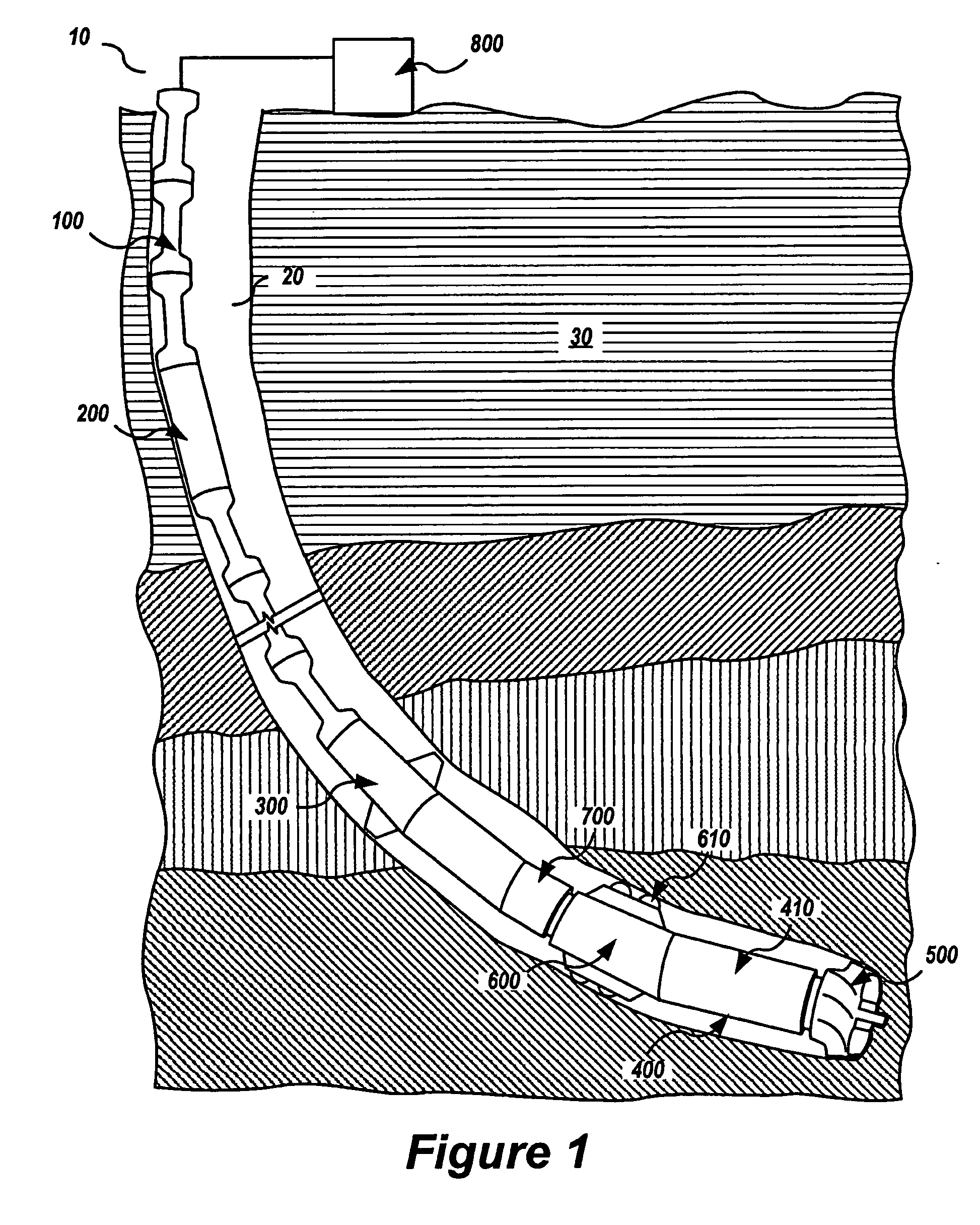
[0012]FIG. 1 schematically illustrates a new drilling method and apparatus. A drill string 10 includes wired drill pipe 100. Drill string 10 is located inside a borehole 20 in a formation 30. Wired drill pipe 100 may include joints of pipe which contain conductors within the drill pipe walls. Wired drill pipe 100 may utilize tubing within the bore of the pipe (e.g., centralized down the center, or biased against the pipe bore inner diameter) to convey conductors. Wired drill pipe 100 may utilize, for example, center stab connectors at each pipe joint, male and female connectors making electrical contact as the drill pipe rotary shouldered connections are made up. In certain embodiments, wired drill pipe 100 may comprise continuous tubing to convey drilling fluid and hang the bottom hole assembly, with conductors either integral with the tubing wall, or contained within a smaller diameter tubing within the bore of the continuous tubing. Wired drill pipe 100 may, for example, convey o...


PUM


Abstract

Methods and apparatuses for drilling a borehole are disclosed. An electric motor electrically and mechanically coupled to a wired drill pipe is provided. The electric motor couples to a shaft that rotates when power is supplied to the electric motor. The shaft is couplable to a drill bit. The wired drill pipe transfers electricity to the electric motor from the surface. Operation of the electric motor rotates the shaft. The drill bit wears away earth to form the borehole in the earth.

Description

CROSS-REFERENCE TO RELATED APPLICATION [0001] This application claims priority to commonly owned U.S. provisional patent application Ser. No. 60 / 549,852, filed Mar. 3, 2004, entitled “Rotating Systems Associated with Drill Pipe,” by Daniel D. Gleitman, Paul F. Rodney, and James H. Dudley.BACKGROUND [0002] In traditional systems for drilling boreholes, rock destruction is carried out via rotary power conveyed by rotating the drill string at the surface using a rotary table or by rotary power derived from mud flow downhole using, for example, a mud motor. Through these modes of power provision, traditional bits such as tri-cone, polycrystalline diamond compact (“PDC”), and diamond bits are operated at speeds and torques supplied at the surface rotary table or by the downhole motor. [0003] In some circumstances and under some drilling conditions when using these traditional techniques, the drilling rate (or rate of penetration, “ROP”) may be compromised. When that occurs, the operator ...

Claims


Application Information

Patent Timeline
IPC IPC(8): E21B4/00E21B4/04E21B4/18E21B7/24E21B10/36E21B17/10E21B41/00
CPCE21B4/04E21B4/18E21B41/0085E21B17/1057E21B7/24
Inventor GLEITMAN, DANIEL D.RODNEY, PAUL F.DUDLEY, JAMES H.
Owner HALLIBURTON ENERGY SERVICES INC
Why Eureka
Try Eureka