Method and system for mass analysis of samples

a mass analyzer and sample technology, applied in the direction of particle separator tube details, instruments, separation processes, etc., can solve the problems of overlap of packets, spurious mass spectra, and longer analysis tim

Active Publication Date: 2005-09-08
DH TECH DEVMENT PTE +2
View PDF21 Cites 16 Cited by
  • Summary
  • Abstract
  • Description
  • Claims
  • Application Information

AI Technical Summary

Benefits of technology

[0010] The present invention seeks to address the aforementioned waste of sample by obviating the need to wait significantly between the electrostatic pulses that act on the ions. In accordance with the method of the invention, a plurality of beams that are offset to propagate along different paths are produced. This offset ensures that each of the plurality of beams does not interfere at the detection regions.

Problems solved by technology

In particular, the waiting time must be long enough to ensure that the lighter and faster ions of a trailing packet will not pass the heavier and slower ions of a preceding packet, which would result in some overlap of the packets.
For this reason, in the traditional pulse-and-wait approach, the release of an ion packet is timed to ensure that the heaviest ions of a preceding packet reach the detector before any overlap or “crosstalk” can occur, which overlap could lead to spurious mass spectra.
Aside from resulting in a longer analysis time, long waiting times between pulses also result in sample waste.
Thus, between pulses, the production of ions by these two methods is essentially incessant.
When the sample being tested is in short supply or is expensive, waste of the sample material can present a serious problem.

Method used


Image

  • Method and system for mass analysis of samples
  • Method and system for mass analysis of samples
  • Method and system for mass analysis of samples

Examples


Embodiment Construction

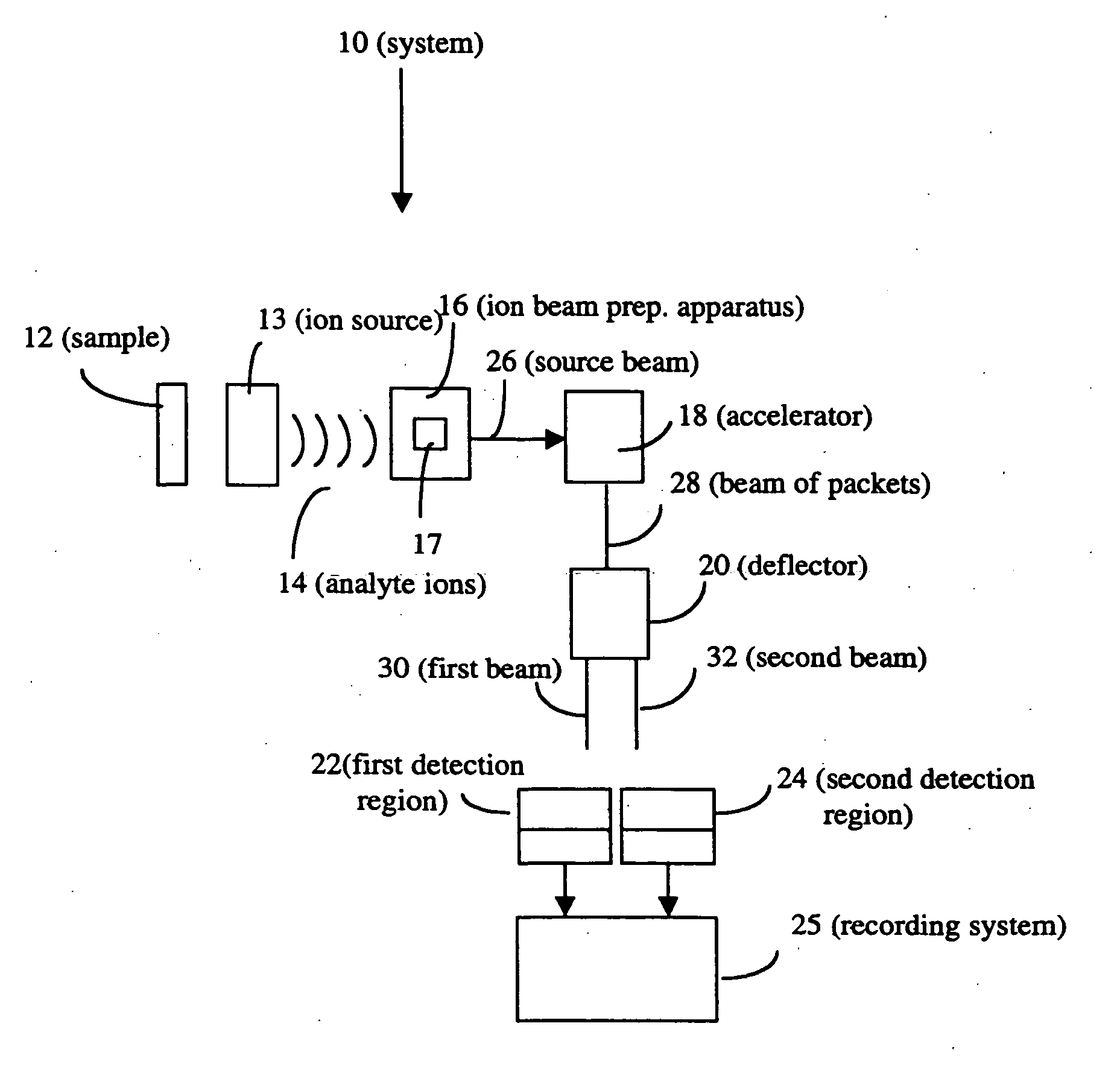
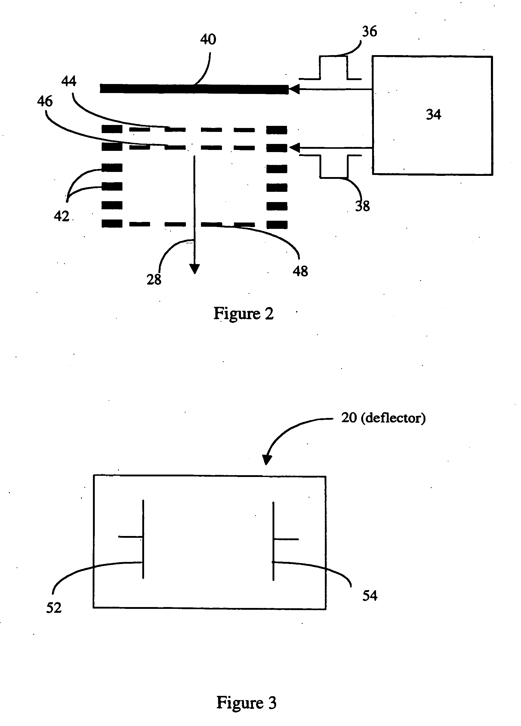
[0021]FIG. 1 shows a mass analysis system 10 for analyzing a sample 12, according to one embodiment of the present invention. The system 10 includes an ion source 13 producing analyte ions 14, an ion beam preparation apparatus 16, an accelerator 18, a deflector 20, a first detection region 22 a second detection region 24, and a recording system 25.

[0022] The ion source 13 produces ions from the sample. For example, the ion source 13 can include an ESI or an orthogonal MALDI ionizer, as known to those of ordinary skill. Analyte ions 14 from the ion source 13, which derives from the sample 12, are processed by the ion beam preparation apparatus 16 to produce a source beam 26 of analyte ions. The ion beam preparation apparatus 16 can include several components, such as a collimator 17, ion-optical electrodes (not shown), a quadrupole ion guide (not shown), an ion filter, such as a mass filter (not shown) and a collision cell (not shown).

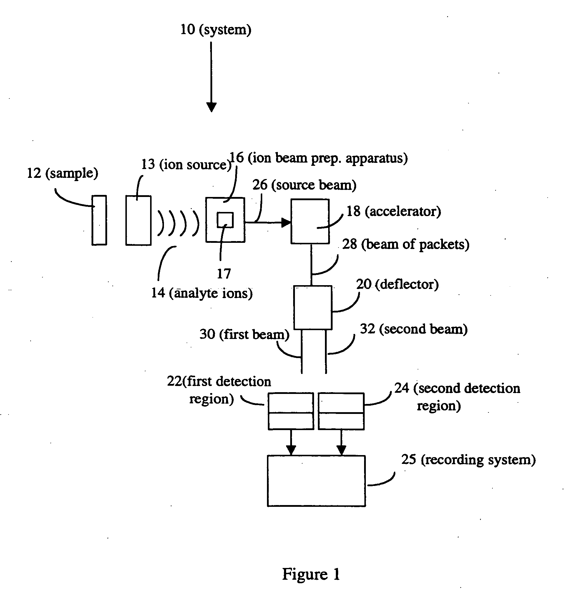
[0023] The accelerator 18 pulses the source bea...


PUM

PropertyMeasurementUnit
pulsing frequencyaaaaaaaaaa
voltageaaaaaaaaaa

Abstract

A system and method of analyzing a sample is described. The system includes an ion source and a deflector for producing a plurality of ion beams each of which is detected in distinct detection regions. A detection system uses the information obtained from the detection region to analyze the sample.

Description

FIELD OF THE INVENTION [0001] The invention relates to analysis of samples using a time-of-flight mass analyzer. BACKGROUND OF THE INVENTION [0002] Mass spectrometry is a powerful method for identifying analytes in a sample. Applications are legion and include identifying biomolecules, such as carbohydrates, nucleic acids and steroids, sequencing biopolymers such as proteins and saccharides, determining how drugs are used by the body, performing forensic analyses, analyzing environmental pollutants, and determining the age and origins of specimens in geochemistry and archaeology. [0003] In mass spectrometry, a portion of a sample is transformed into gas phase analyte ions. The analyte ions are typically separated in the mass spectrometer according to their mass-to-charge (m / z) ratios and then collected by a detector. The detection system can then process this recorded information to produce a mass spectrum that can be used for identification and quantitation of the analyte. [0004] T...

Claims


Application Information

Patent Timeline
Patent Type & Authority Applications(United States)
IPC IPC(8): G01N27/62H01J49/00H01J49/02H01J49/10H01J49/40
CPCH01J49/0031H01J49/40H01J49/061H01J49/009
Inventor CHERNUSHEVICH, IGOR
Owner DH TECH DEVMENT PTE
Why Eureka
Try Eureka