Image forming apparatus

a technology of forming apparatus and nozzle plane, which is applied in the direction of thin material processing, printing, and article delivery, etc., can solve the problems of image quality deterioration, image failure, and nozzle plane contamination of the head and paper itsel

Inactive Publication Date: 2005-09-08
RICOH KK
View PDF22 Cites 75 Cited by
  • Summary
  • Abstract
  • Description
  • Claims
  • Application Information

AI Technical Summary

Benefits of technology

[0019] It is a general object of the present invention to provide an improved and useful image forming apparatus in which the above-mentioned problems are eliminated.
[0020] A more specific object of the present invention is to provide an image forming apparatus which improves a printing speed and convenience of use.
[0022] According to the present invention, since the image forming apparatus has the belt conveyance mechanism that electrostatically attaches the paper and conveys the paper in a direction perpendicular to a carding direction of the paper, the paper can be subjected to a recording operation while being conveyed in a transverse mesh direction, which improves a printing speed and also improves convenience of use.
[0028] According to the above-mentioned invention, since the image forming apparatus has the belt conveyance mechanism that electrostatically attaches the paper and conveys the paper in a direction perpendicular to a carding direction of the paper and also has a paper supply mechanism that accommodates the paper to be supplied to the belt conveyance mechanism so that paper is set in the paper supply mechanism in a state where a carding direction of the paper is perpendicular to a direction of conveyance of the paper by the belt conveyance mechanism, the paper can be subjected to a recording operation while being conveyed in a transverse mesh direction, which improves a printing speed and also improves convenience of use and further the paper can be set from the front side of the image forming apparatus, which further improves convenience of use of the image forming apparatus.

Problems solved by technology

If a degree of cockling increases, in a worst case, the paper is brought into contact with the nozzle plane of the head, which causes contamination of the nozzle plane of the head and contamination of the paper itself.
However, in the state where a paper is engaged with only one pair of rollers, if a paper lift occurs, an accuracy of feed cannot guaranteed since there is no measures to solve the paper lift or a force to convey the paper cannot be acquired, and, thus, there is a problem in that an image quality deteriorates.
If a such a paper having a carding mesh is conveyed in a direction in which the carding direction is perpendicular to a conveying direction, the nozzle plane and the paper may contact with each other since the paper bends largely in a direction along the conveying direction due to cockling caused by adhesion of liquid droplets as mentioned above, which results in a problem peculiar to an inkjet recording apparatus that an image failure occurs.

Method used


Image

  • Image forming apparatus
  • Image forming apparatus
  • Image forming apparatus

Examples


Embodiment Construction

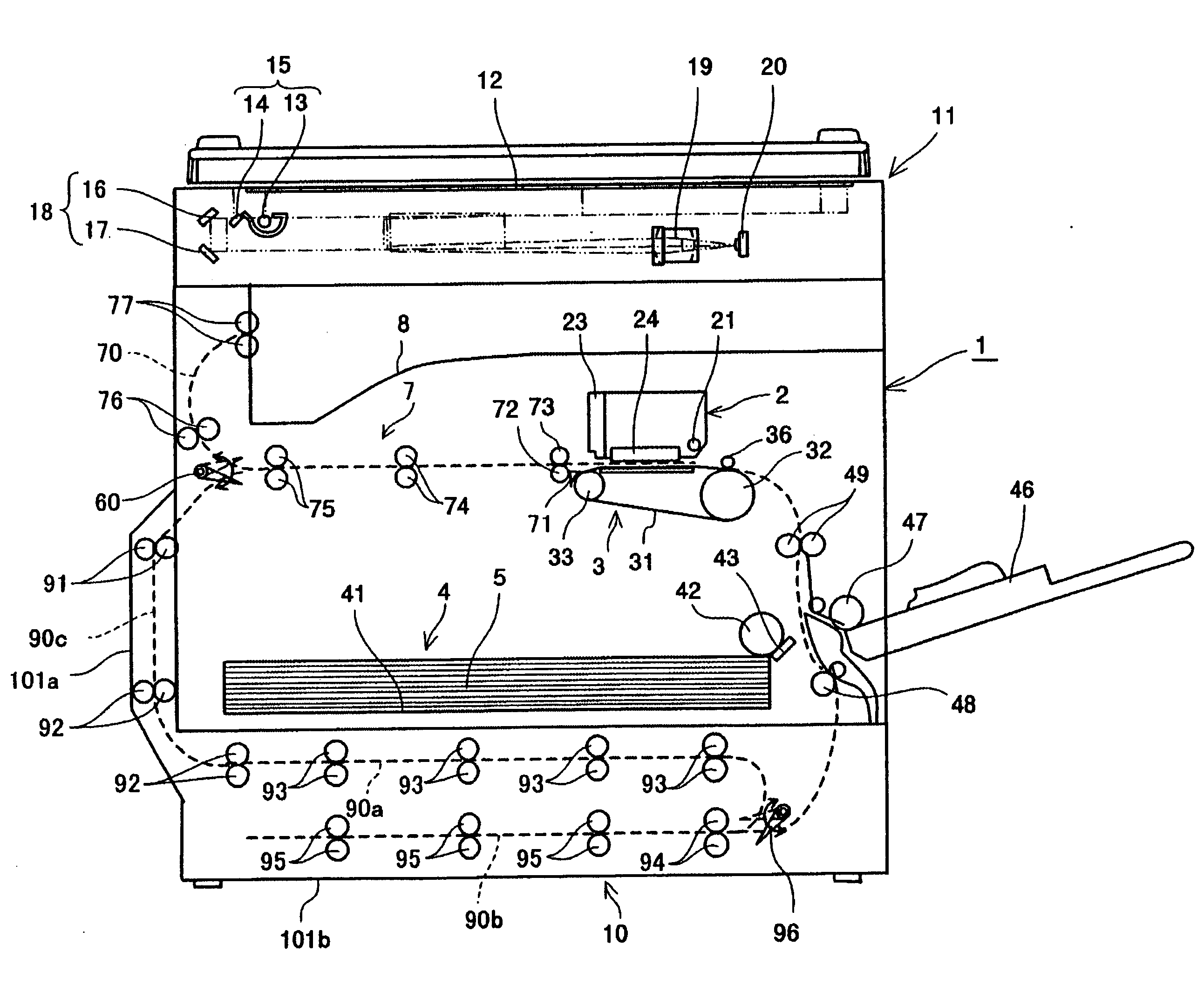
[0046] A description will now be given, with reference to FIGS. 4 through 10, of an image forming apparatus according to a first embodiment of the present invention.

[0047]FIG. 4 is a side view of the image forming apparatus according to the first embodiment of the present invention shown in an outline of the entire structure. FIG. 5 is a plan view of an image forming part and a sub-scanning conveyance part in the image forming apparatus shown in FIG. 4. FIG. 6 is a perspective view of a carriage part of the image forming apparatus shown in FIG. 4. FIG. 7 is a perspective view of an ink supply system to a head of the image forming apparatus shown in FIG. 4. FIG. 8 is a side view of a part of a paper eject conveyance part and the sub-scanning conveyance part of the image forming apparatus shown in FIG. 4. FIG. 9 is an illustration for explaining a paper supply cassette and a setting direction of papers. FIG. 10 is a perspective view of a part of the paper eject conveyance part of the...


PUM


Abstract

An inkjet recording apparatus provides an improved printing speed and improved convenience of use. A recording head discharges droplets of a recording liquid onto a paper so as to form an image on the paper. A belt conveyance mechanism has a belt onto which the paper is electrostatically attached. The paper attached onto the belt is conveyed in a direction perpendicular to a carding direction of the paper.

Description

BACKGROUND OF THE INVENTION [0001] 1. Field of the Invention [0002] The present invention generally relates to image forming apparatuses and, more particularly, to an image forming apparatus that is capable of forming an image by a recording liquid while conveying a paper in a transverse direction. [0003] 2. Description of the Related Art [0004] Inkjet recording apparatuses are known as image forming apparatuses incorporated in a printer, a facsimile machine, a copy machine and a combination machine of a printer, a facsimile machine and a copy machine that perform image formation (recording, printing and copying may be used as equivalent words) by causing droplets of a recording liquid (hereinafter, may be referred to as ink droplets) to adhere onto a paper, while conveying the paper, using a recording head (image forming means) constituted by a liquid droplet discharge head which discharges droplets of a recording liquid. [0005] As the liquid droplet discharge head, there are used ...

Claims


Application Information

Patent Timeline
Patent Type & Authority Applications(United States)
IPC IPC(8): B41J2/01B41J11/02B41J13/00B41J13/08B65H5/00B65H29/20B65H29/56
CPCB41J13/10B41J13/08
Inventor NISHIDA, HAJIMENONAKA, MANABUYOSHIMIZU, EIKINARUSE, SHINICHIROKAWASHIMA, YASUHIROSUEOKA, HIDEKIMORINO, TETSUISHIKAWA, KAZUMASAYOUDA, YASUNOBUFUJITA, AKIHIROASANUMA, SHOJISAKAKITANI, MASATOSHIKUDOH, TAKUITO, SHIGEYUKIDOHKI, YOHZOHWATANABE, KOJI
Owner RICOH KK
Why Eureka
Try Eureka