
Method of charging a battery

a battery and charging method technology, applied in the field of charging a battery, can solve the problems of not prohibitively expensive for use in certain products, lithium-based batteries have a low self-discharge rate, and the cost of lithium-based batteries is high

Inactive Publication Date: 2005-09-08
GALAXY POWER
View PDF1 Cites 42 Cited by
  • Summary
  • Abstract
  • Description
  • Claims
  • Application Information

AI Technical Summary

Benefits of technology

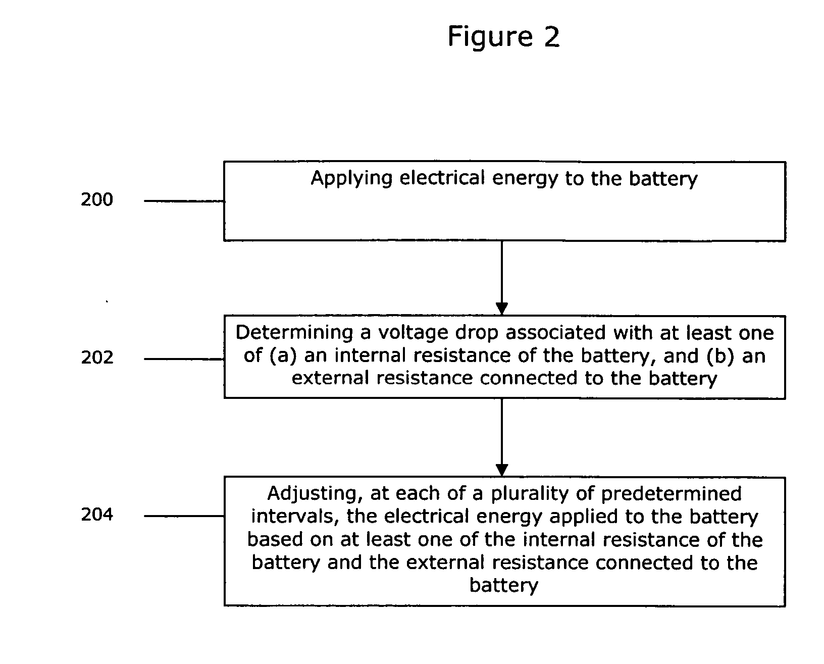
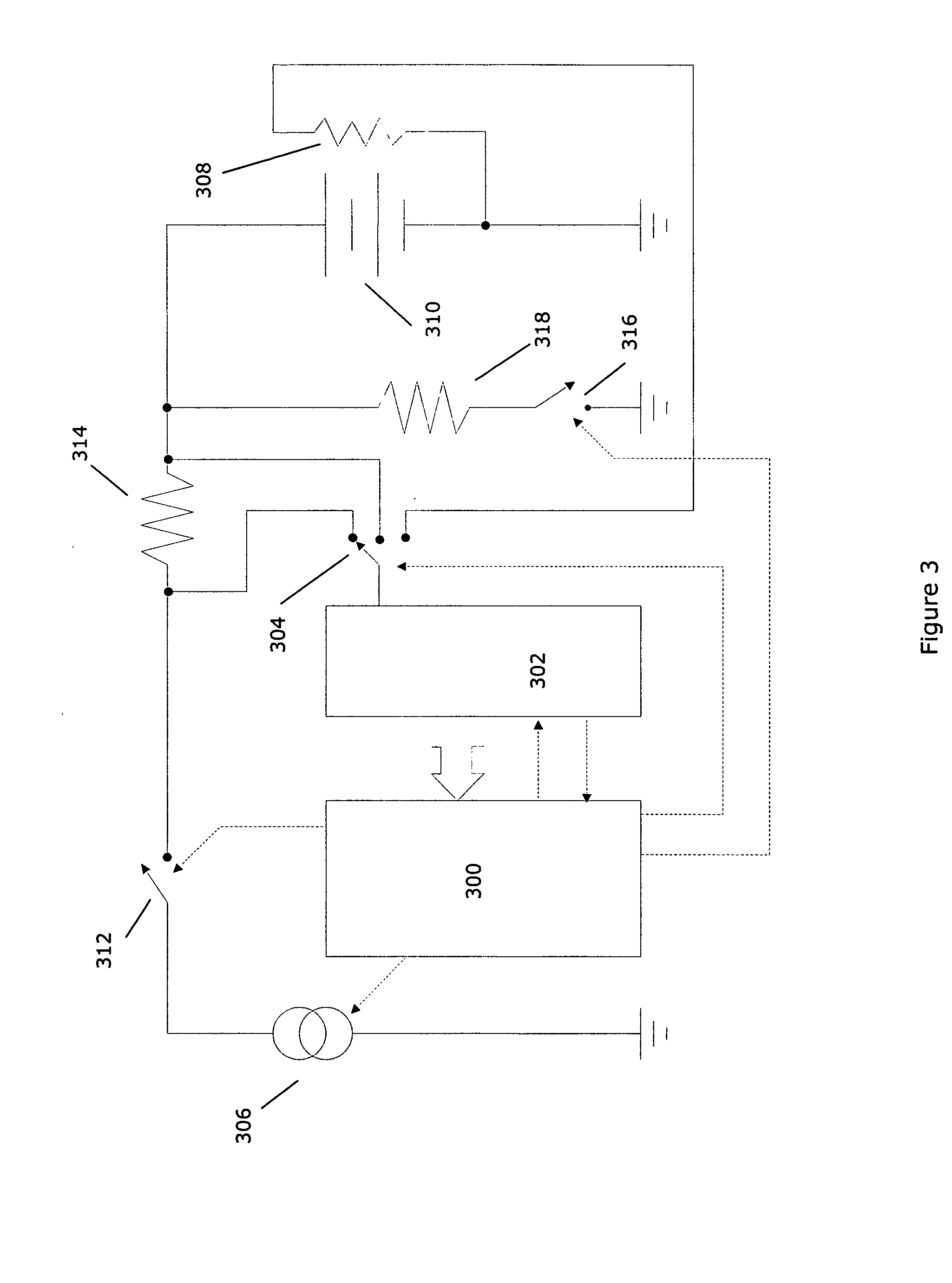
[0014] According to yet another exemplary embodiment of the present invention, an electronic device is provided. The electronic device includes a battery having an internal resistance and an external resistance connected to the battery. The electronic device also includes processor. The processor controls an electrical energy source for applying electrical energy to the battery. Further, the processor adjusts, after each of a plurality of predetermined intervals, the electrical energy applied to the battery based on at least one of the internal resistance of the battery and the external resistance connected to the battery.

Problems solved by technology

Further, lithium-based batteries have a low rate of self-discharge.
Although lithium-based batteries may be more costly than certain other batteries (e.g., nickel-cadmium (Ni—Cd) and nickel-metal-hydride batteries (Ni-MH)), they are not prohibitively expensive for use in certain products.
For example, attempting to charge lithium-based batteries beyond 4.2 volts per cell may permanently damage the battery and may even result in an explosion of the battery.
Further, over discharging lithium-based batteries may also result in irreversible changes to the batteries.
Additionally, lithium-based batteries that supply excessive output current may be damaged (or even explode), and as such, manufacturers often incorporate an overcurrent protection device (e.g., a PTC fuse) within the battery pack.
Unfortunately, such a charging cycle duration (i.e., 2½ to 3½ hours) is excessive in comparison to charging times for nickel-cadmium and nickel-metal-hydride batteries.
For example, Ni-MH batteries can be charged in approximately 1 hour, where the limitation on charging time is related to their exothermic charging characteristics.
Thus, the relatively long charging cycle of lithium-based batteries as compared to other battery chemistries is one of their less desirable characteristics.
Another undesirable characteristic of lithium-based batteries is known as “capacity fade.” More specifically, each time a lithium-based battery is charged it loses a small percentage of its storage capacity.

Method used


Image

  • Method of charging a battery
  • Method of charging a battery
  • Method of charging a battery

Examples


Embodiment Construction

[0023] Preferred features of embodiments of this invention will now be described with reference to the figures. It will be appreciated that the spirit and scope of the invention is not limited to the embodiments selected for illustration. It is contemplated that any of the configurations and materials described hereafter can be modified within the scope of this invention.

[0024] U.S. Pat. No. 5,600,226 relates to battery charging techniques and is incorporated by reference herein for its teachings related to batteries and battery charging.

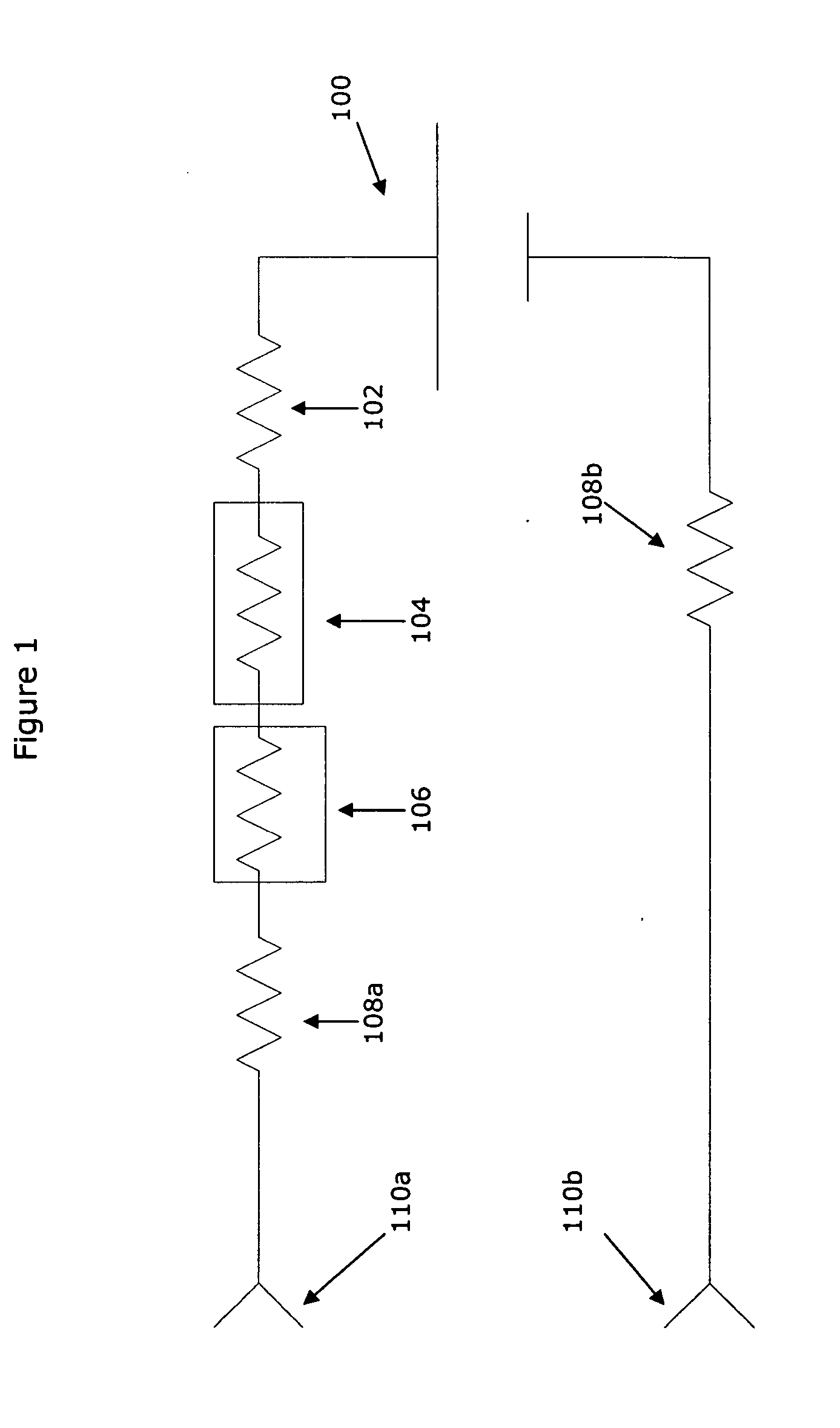
[0025] In relation to the battery charging methods described herein, electrical energy is applied to the battery. For example, during a constant current phase of a charging cycle, this electrical energy may be viewed as being supplied by a constant current source. Conversely, during a constant voltage phase of a charging cycle, this electrical energy may be viewed as being supplied by a constant voltage source. It is contemplated that the electric...


PUM


Abstract

A method of charging a battery having an internal resistance and an external resistance connected to the battery includes applying electrical energy to the battery. The method also includes adjusting, at a plurality of predetermined intervals, the electrical energy applied to the battery based on at least one of the internal resistance of the battery and the external resistance connected to the battery.

Description

FIELD OF THE INVENTION [0001] The present invention relates to charging a battery, and more particularly, to charging a battery by dynamically compensating for resistance associated with the battery. BACKGROUND OF THE INVENTION [0002] As the use of portable powered devices increases (e.g., portable battery operated electronic devices, cordless power tools, etc.), interest in varying battery technologies has also increased. For example, lithium-based (e.g., lithium-ion, lithium-polymer, etc.) batteries have become increasingly popular in battery powered portable electronics equipment (e.g., cameras, laptop PCs, cordless telephones, cellular telephones, personal digital assistants (PDAs), etc.). [0003] When used in these applications, lithium-based battery technology possesses certain technological advantages over alternate technologies such as a high volumetric efficiency and a high mass efficiency. More specifically, for a given weight and volume, lithium-based batteries are capable...

Claims


Application Information

Patent Timeline
Patent Type & Authority Applications(United States)
IPC IPC(8): H02J7/00
CPCH02J7/0077H02J7/00712
Inventor ARNOLD, EDWARD H.ROGERS, BRUCE J.
Owner GALAXY POWER
Learn More