Temperature controlled MEMS resonator and method for controlling resonator frequency

a mems resonator and temperature control technology, applied in the direction of resistance/reactance/impedence, instruments, semiconductor devices, etc., can solve the problems of heating elements, not normally being the case, and consuming a significant amount of power, among other things

Active Publication Date: 2005-09-08
ROBERT BOSCH GMBH
View PDF10 Cites 82 Cited by
  • Summary
  • Abstract
  • Description
  • Claims
  • Application Information

AI Technical Summary

Benefits of technology

[0019] In a second principal aspect, the present invention is a MEMS resonator that has a resonant frequency which is defined in relation to an operating temperature. The MEMS resonator includes first and second substrate anchors, each including electrical contacts, and a first beam, comprised of a conductive or semi-conductive material, which is electrically connected between the electrical contacts. The MEMS resonator also includes a first moveable beam having a first end that is thermally coupled to the first beam and an electrical source, coupled to the electrical contacts, to provide a controlled current to the first electrical contact and thereby heat the first beam.

Problems solved by technology

This, however, will not normally be the case as thermally induced changes to the Young's modulus tend to change the mechanical stiffness of the beam.
Such a configuration, and, in particular, the heating element, may, among other things, consume a significant amount of power because of the large heat loss to the surroundings / environment.
In addition, such a configuration employs unfocused or non-specific heating of the entire micromechanical resonator.

Method used


Image

  • Temperature controlled MEMS resonator and method for controlling resonator frequency
  • Temperature controlled MEMS resonator and method for controlling resonator frequency
  • Temperature controlled MEMS resonator and method for controlling resonator frequency

Examples


Embodiment Construction

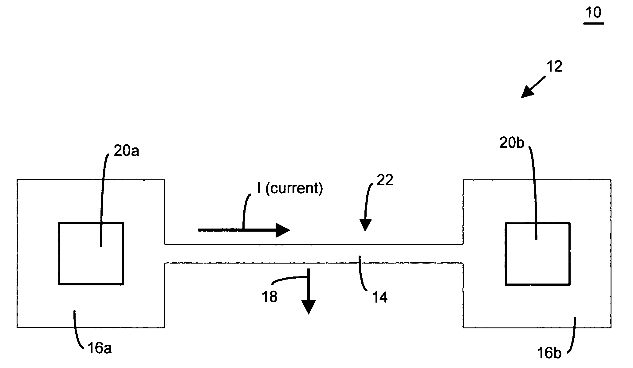
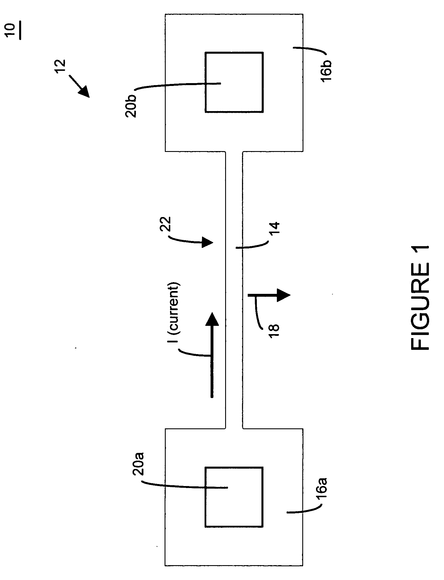
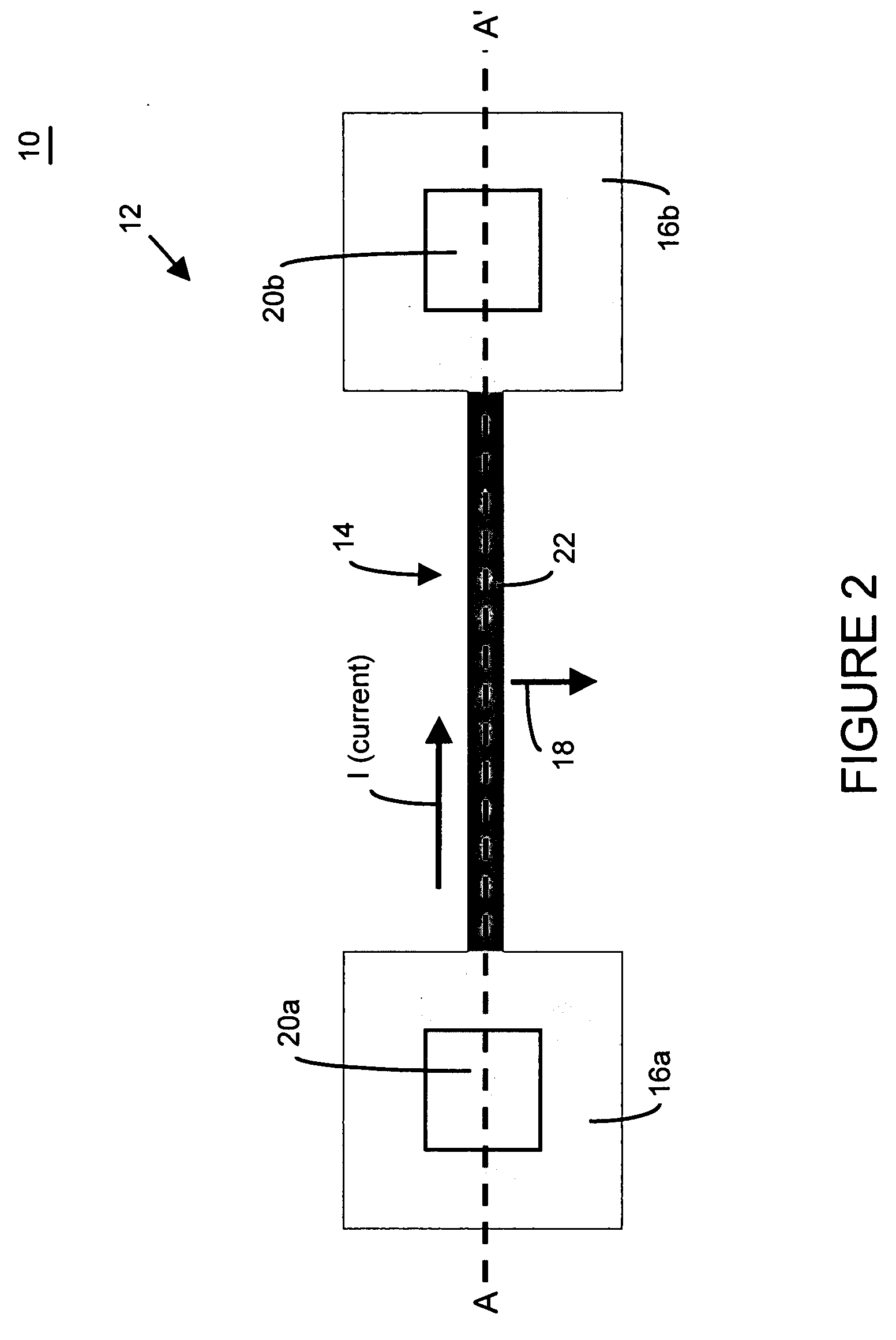
[0077] There are many inventions described and illustrated herein. In a first aspect, the present invention is directed to a microelectromechanical resonator and method of fabricating, manufacturing and / or controlling a microelectromechanical resonator having mechanical structures that include integrated heating and / or temperature sensing elements. In this regard, in one embodiment, the mechanical structure is configured, in conjunction with the heating circuitry, to integrate the heating element within the moveable beam(s) such that a constant temperature and / or relatively constant temperature (for example, ±5%, and preferable less than 1%) exists over the length of the moveable beam. In this regard, the heating element is, or incorporated into, the moveable beam(s) is resistively heated by a heating current (I) flowing within, in and / or on the moveable beam(s).

[0078] With reference to FIG. 1, in a first embodiment of this aspect of the present invention, MEMS resonator 10 include...


PUM


Abstract

There are many inventions described and illustrated herein. In one aspect, the present invention is directed to a temperature compensated microelectromechanical resonator as well as fabricating, manufacturing, providing and / or controlling microelectromechanical resonators having mechanical structures that include integrated heating and / or temperature sensing elements. In another aspect, the present invention is directed to fabricate, manufacture, provide and / or control microelectromechanical resonators having mechanical structures that are encapsulated using thin film or wafer level encapsulation techniques in a chamber, and including heating and / or temperature sensing elements disposed in the chamber, on the chamber and / or integrated within the mechanical structures. Other aspects of the inventions will be apparent from the detailed description and claims herein.

Description

BACKGROUND [0001] This invention relates to microelectromechanical systems and / or nanoelectromechanical systems (collectively hereinafter “microelectromechanical systems”) and techniques for fabricating microelectromechanical systems; and more particularly, in one aspect, for fabricating, manufacturing, providing and / or controlling microelectromechanical resonators having mechanical structures that include integrated heating and / or temperature sensing elements; and in another aspect for fabricating, manufacturing, providing and / or controlling microelectromechanical resonators having mechanical structures that are encapsulated using thin film or wafer level encapsulation techniques in a chamber, and include heating and / or temperature sensing elements disposed in the chamber, on the chamber and / or integrated within the mechanical structures. [0002] Many conventional micromechanical structures are based on the reaction (for example, oscillation, deflection or torsion) of a beam structu...

Claims


Application Information

Patent Timeline
Patent Type & Authority Applications(United States)
IPC IPC(8): H03H9/02H03H9/24H03H9/54
CPCH01L2224/48091H01L2924/01019H01L2924/01057H01L2924/01078H01L2924/01079H03H9/02338H03H9/02401H03H9/02448H03H9/2426H03H9/2463H03H9/2473H03H9/2478H03H2009/02496H03H2009/02511H03H2009/02527H01L2224/48227H01L2924/00014
Inventor LUTZ, MARKUSPARTRIDGE, AARON
Owner ROBERT BOSCH GMBH
Why Eureka
Try Eureka