Communication timing control apparatus, communication timing control method, node, and communication system

a communication timing control and control method technology, applied in the field of communication timing control apparatus, communication timing control method, node, communication system, etc., can solve the problems of complex process by which time slots are assigned dynamically to nodes, affecting the operation of communication systems, and restricting the number of channels that can be used simultaneously. , to achieve the effect of avoiding signal collision

Inactive Publication Date: 2005-09-08
OKI ELECTRIC IND CO LTD
View PDF6 Cites 9 Cited by
  • Summary
  • Abstract
  • Description
  • Claims
  • Application Information

AI Technical Summary

Benefits of technology

[0009] An object of the present invention is to provide a communication timing control method that avoids signal collisions in a communication system by autonomous control of the communicating nodes.
[0011] Still another object is to prevent signal reflection from disturbing communication timing control.
[0012] Yet another object is to prevent communication timing control from being disturbed by signals from sources that are not part of the communication system.
[0016] By adjusting their internal transition timings, a group of neighboring nodes can autonomously reach a steady state in which the state variable signals transmitted from different nodes are separated by intervals that can be used as time slots for data communication. When the system undergoes a change, the nodes affected by the change can adjust autonomously and reach a new steady state. By determining the validity of the state variable signals, the nodes can avoid having their communication timing control disturbed by reflected signals and other extraneous signals.

Problems solved by technology

A disadvantage of CSMA is that it severely restricts the number of channels that can be used simultaneously.
A weakness of the TDMA system is that if the administrative node malfunctions, the entire communication system may be brought down.
The process by which time slots are assigned dynamically to nodes is also complex, making it difficult to respond promptly to changing conditions.

Method used


Image

  • Communication timing control apparatus, communication timing control method, node, and communication system
  • Communication timing control apparatus, communication timing control method, node, and communication system
  • Communication timing control apparatus, communication timing control method, node, and communication system

Examples


first embodiment

[0041] In the first embodiment, each of the nodes is assumed to remain substantially stationary during communication.

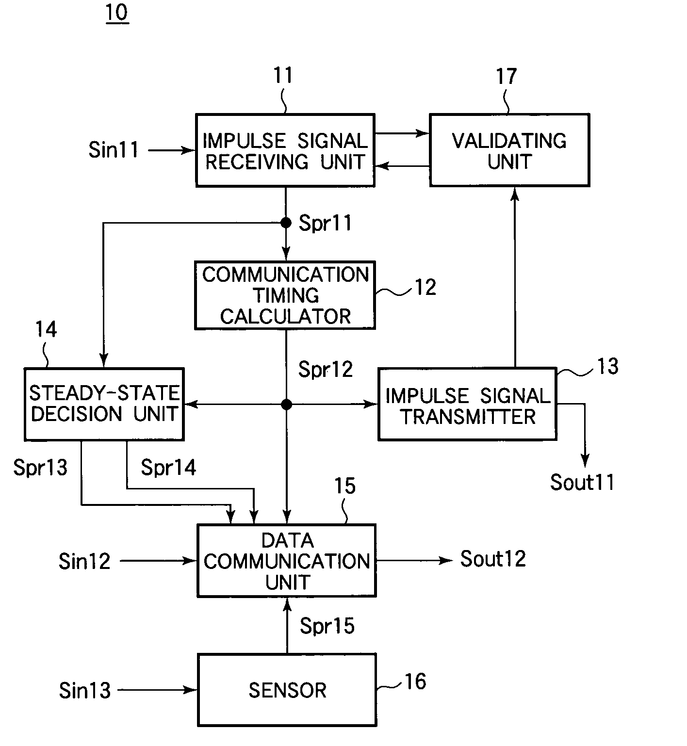
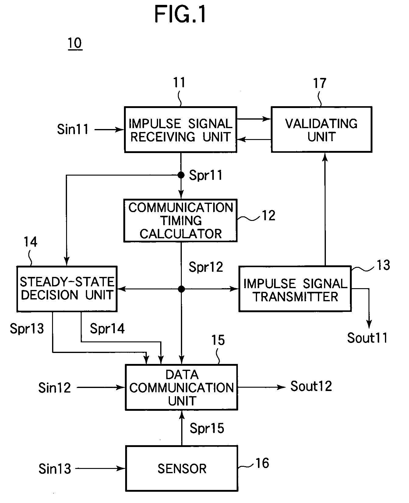
[0042] Each of the plurality of nodes has the functional block structure shown in FIG. 1. The node 10 in FIG. 1 comprises an impulse signal receiving unit 11, a communication timing calculator 12, an impulse signal transmitter 13, a steady-state decision unit 14, a data communication unit 15, a sensor 16, and a validating unit 17. The impulse signal receiving unit 11, communication timing calculator 12, impulse signal transmitter 13, steady-state decision unit 14, and validating unit 17 operate as a communication timing control apparatus.

[0043] The impulse signal receiving unit 11 receives input impulse signals Sin11 transmitted by neighboring nodes. The impulse signals in the first embodiment are timing signals having, for example, a Gaussian waveshape, not including any data or address information. The neighboring nodes include, for example, all nodes within commu...

second embodiment

[0091] In the first embodiment, detection of invalid impulse signals is contingent on the nodes remaining generally stationary. The second embodiment enables invalid impulse signals to be identified even if some or all of the nodes move. In the second embodiment each node counts the number of impulse signals that have been transmitted by the node itself and all its neighboring nodes and adds the current count value (referred to as count information) to the next impulse signal it generates and transmits.

[0092] Referring to FIG. 6, in a node 10A in the second embodiment, the validating unit in the first embodiment is replaced by a count validating unit 18, and the functions of the impulse signal receiving unit 11 and the impulse signal transmitter 13 are slightly altered. The other constituent elements are the same as in the first embodiment, so descriptions will be omitted.

[0093] In the second embodiment, as in the first embodiment, the impulse signal receiving unit 11 receives an ...

third embodiment

[0114] The count information added to each impulse signal in the second embodiment can be regarded as a type of identifying (ID) information that varies regularly from one impulse signal to the next. The third embodiment also adds ID information to the impulse signals, but varies the ID information irregularly.

[0115] In the third embodiment, each node generates random ID information to add to the output impulse signals it transmits. A node receiving an impulse signal extracts the ID information and decides whether or not the input impulse signal is valid by comparing the extracted ID information with internally retained ID information. If the input impulse signal is valid, the node retains the extracted ID information for a predetermined period of time.

[0116] Referring to FIG. 8, in a node 10B in the second embodiment the count validating unit in the second embodiment is replaced by an ID validating unit 19 and an ID generator 20, and the functions of the impulse signal receiving ...


PUM


Abstract

Each node in a communication system receives state variable signals from other nodes indicating the internal operating states or internal timing of the other nodes, and transmits a state variable signal indicating its own internal operating state or timing. Each node also determines whether each received state variable signal is valid. Transitions in the internal operating state or timing of a node take place at a basic transition rate but at times adjusted according to the valid state variable signals received from other nodes. A group of neighboring nodes transmitting data signals can thereby autonomously reach a steady state in which their data signals do not collide, without having their timing control disrupted by reflected state variable signals or other invalid state variable signals.

Description

BACKGROUND OF THE INVENTION [0001] 1. Field of the Invention [0002] The present invention relates to a communication timing control apparatus, a communication timing control method, a node, and a communication system, more particularly to the avoidance of data transmission collisions in a communication system with a plurality of nodes. [0003] 2. Description of the Related Art [0004] Known methods by which a plurality of spatially distributed nodes can transmit data without collisions include time division multiple access (TDMA) and carrier sense multiple access (CSMA), the latter including carrier sense multiple access with collision avoidance (CSMA / CA) and carrier sense multiple access with collision detection (CSMA / CD). A discussion of these methods can be found in, for example, Waiyaresu LAN Akitekucha (Wireless LAN Architecture), edited by Matsushita and Nakagawa, Kyoritsu Shuppan, 1996, pp. 47, 53-59, and 69 (in Japanese). [0005] In the CSMA methods, a node with data to transmi...

Claims


Application Information

Patent Timeline
Patent Type & Authority Applications(United States)
IPC IPC(8): H04J3/17H04J3/00H04J3/06H04L5/22H04L7/00H04L12/28H04Q11/04
CPCH04W48/08H04W48/16H04W12/06H04J3/0676H04W56/00H04W12/069
Inventor YAO, TAKETSUGUDATE, MASAAKIMORITA, YUKIHIROFUKUNAGA, SHIGERU
Owner OKI ELECTRIC IND CO LTD
Why Eureka
Try Eureka