Successive interference cancellation in a generalized RAKE receiver architecture

a receiver architecture and receiver technology, applied in the direction of multi-channel communication, transmission, electrical equipment, etc., can solve the problems of limiting the capacity of cdma systems, conventional single-user receivers may not be able to detect signals, and the complexity of optimal mud systems increases exponentially with the number of users

Active Publication Date: 2005-09-08
OPTIS WIRELESS TECH LLC
View PDF5 Cites 181 Cited by
  • Summary
  • Abstract
  • Description
  • Claims
  • Application Information

AI Technical Summary

Benefits of technology

[0011] Thus, in one or more exemplary embodiments, the present invention comprises a method of processing a received composite communication signal that includes two or more signals of interest. The method comprises individually detecting the signals of interest in successive ones in a series of signal detection stages, canceling the signal of interest detected in each stage with respect to an input signal provided to the next stage in the series, and wherein, in each stage, detecting a signal of interest comprises generating combining weights as a function of impairment correlations between despread values of the input signal for that stage, and combining the despread values according to the combining weights. Complementing the above method, an exemplary receiver ci

Problems solved by technology

While conventional RAKE receivers improve the SNR of the received signal, they do not address interference caused by other users' signals, i.e., multiple access interference (MAI) and intersymbol interference (ISI).
MAI and ISI limit the capacity of CDMA systems.
ISI is due to distortion of the transmitted signal that occurs in multipath channels.
When the number of users becomes large, conventional single-user receivers may not be able to detect signals from weak users because of high interference levels.
While MUD systems are effective in reducing MAI, the complexity of optimal MUD systems increases exponentially with the number of users.
In typical oper

Method used


Image

  • Successive interference cancellation in a generalized RAKE receiver architecture
  • Successive interference cancellation in a generalized RAKE receiver architecture
  • Successive interference cancellation in a generalized RAKE receiver architecture

Examples


Embodiment Construction

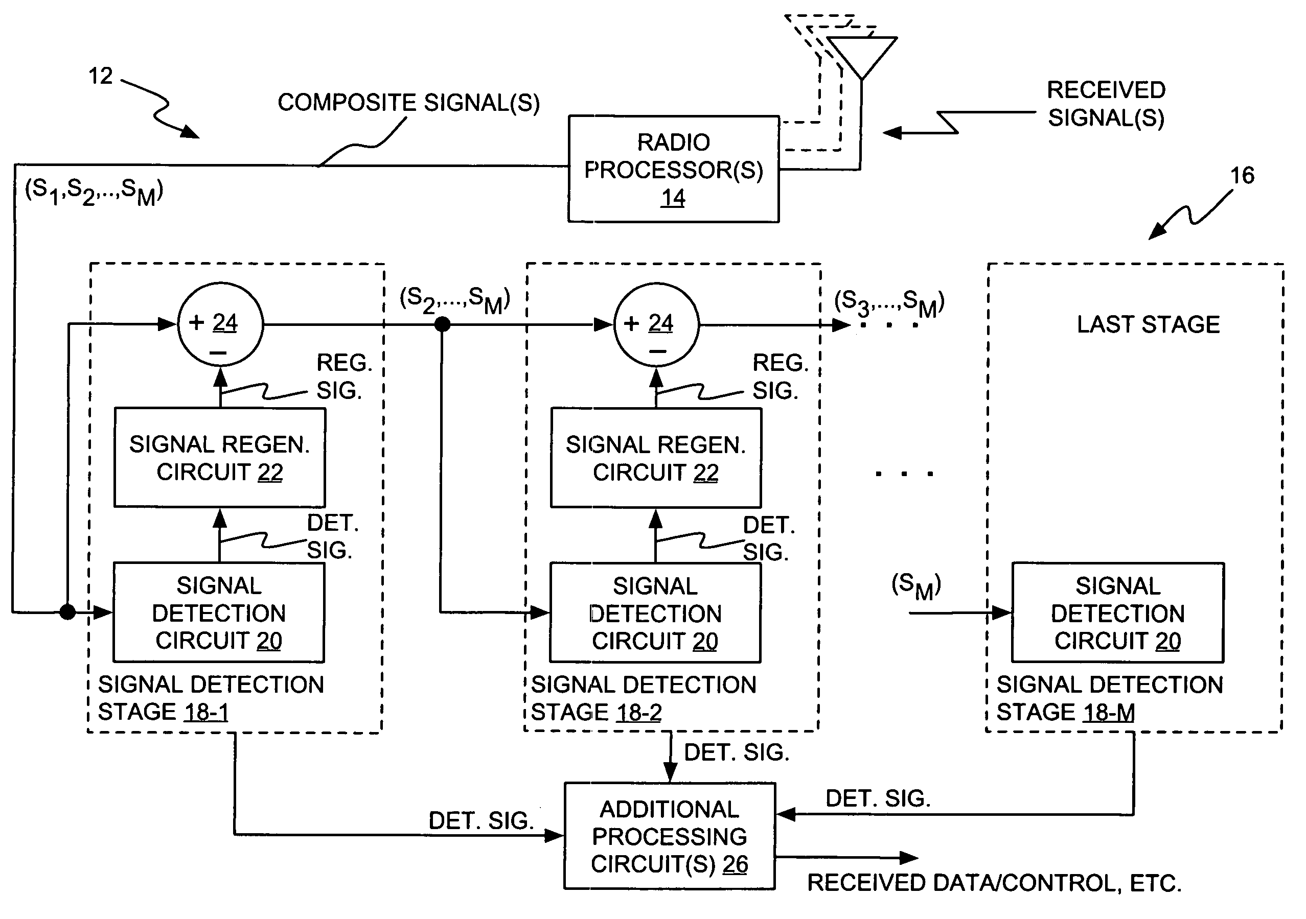
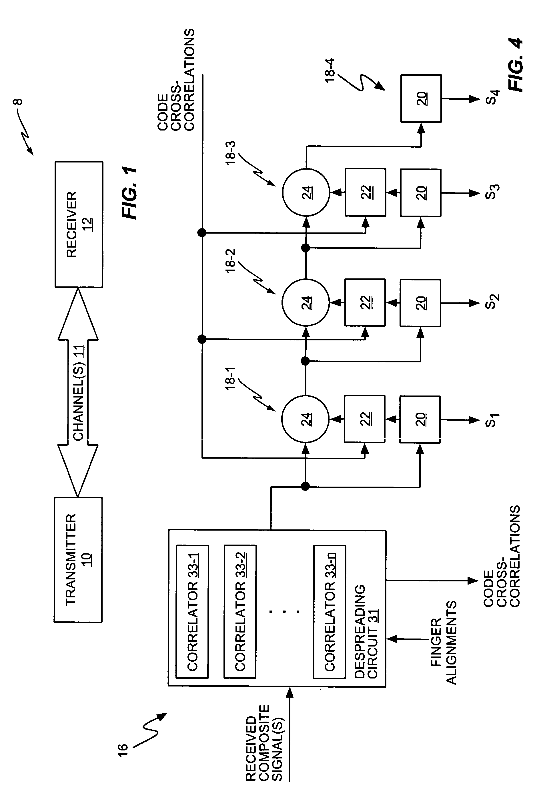
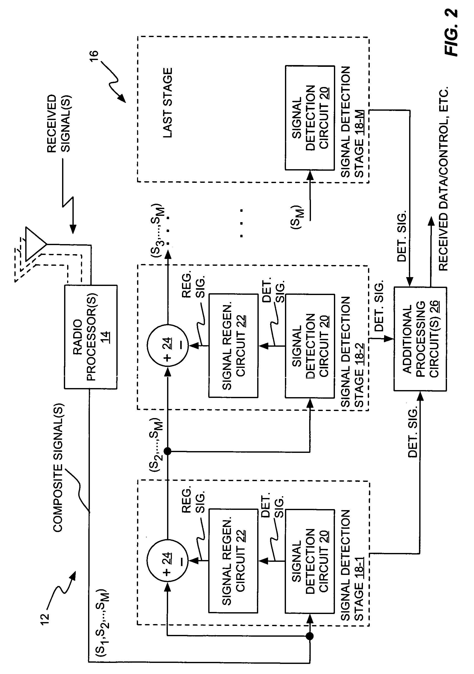
[0024] Discussing and illustrating details in the many exemplary embodiments of the present invention necessarily involves a certain level of complexity. Such complexities are explored in the exemplary details given later herein but an initial understanding of the present invention's broader aspects may be gained with reference to the relatively simple diagram given in FIG. 1. However, before discussing FIG. 1, it should be understood that the present invention broadly involves the application of GRAKE-based signal detection in combination with successive interference cancellation.

[0025] As used herein the term “GRAKE” connotes a RAKE combining circuit and / or combining method that calculates impairment correlations between the streams of despread values being RAKE combined by the circuit. Such impairments arise, for example, because of MAI, aggressive spreading code reuse, channel fading conditions, etc. Note that own-cell MAI may be accounted for as interference, while other-cell ...


PUM


Abstract

A receiver includes a receiver circuit that decodes multiple signals of interest contained in a composite received signal. The receiver comprises a plurality of successive signal detection stages to detect respective signals contained in the composite received signal. Each detection circuit comprises at least one Generalized RAKE combining circuit and generates a detected signal at an output. Each but the last stage further comprises a signal regeneration circuit that cancels the signal of interest detected by that stage from a stage input signal provided to the next stage such that successive detection of the signals of interest benefits from cumulative cancellation of the previously detected signals.

Description

BACKGROUND OF THE INVENTION [0001] Emerging third-generation (3G) wireless communication systems support several different kinds of services including voice, high-speed packet data and multimedia services. Further, 3G systems allow users to access several different services simultaneously. To meet the demand for these services, future wireless communication systems will need to provide much higher capacity than second-generation (2G) systems. Greater capacity can be obtained by allocating additional bandwidth, which is unlikely to occur, or by utilizing the allocated bandwidth more efficiently. [0002] WCDMA (Wideband Code Division Multiple Access) is one technology that is expected to help fulfill the demand for 3G services. WCDMA is a multiple access technology for wireless communications over wideband frequency channels. Like narrowband Code Division Multiple Access (CDMA), WCDMA employs spreading codes to spread narrowband signals over the full width of the frequency channel. Eac...

Claims


Application Information

Patent Timeline
IPC IPC(8): H04B1/707H04J99/00
CPCH04B1/707H04B2201/709727H04B1/7107H04B1/712H04B1/7105H04B1/71075H04B1/7115H04B1/71072
Inventor GRANT, STEPHEN JAMESCHENG, JUNG-FUKRASNY, LEONIDMOLNAR, KARL JAMESWANG, YI-PIN ERIC
Owner OPTIS WIRELESS TECH LLC
Why Eureka
Try Eureka