Diffractometer

a diffractionometer and axis technology, applied in the direction of instruments, electrical equipment, crystal growth process, etc., can solve the problems of excessive time taken to align the sample and axis, difficult use of goniometers during growth,

Active Publication Date: 2005-09-08
PANALYTICAL BV
View PDF7 Cites 10 Cited by
  • Summary
  • Abstract
  • Description
  • Claims
  • Application Information

AI Technical Summary

Benefits of technology

[0018] The inventors have realised that by selecting a suitable reflection to carry out the measurements on it is possible to measure a single parameter and have this give directly a value for the vertical lattice parameter of the structure deposited on the structure without needing to measure two parameters to find the lattice parameters both vertically and horizontally. This allows the vertical lattice parameter to be quickly determined.

Problems solved by technology

However, the construction of growth chambers leads to problems for X-ray diffractometers in that their construction necessarily needs to be optimised for growth and not for X-ray diffractometry.
Conventional X-ray diffraction approaches use a goniometer to orient incident and diffracted X-ray beams, but goniometers are difficult to use during growth and generally require a specially designed growth chamber.
However, when a sample is mounted in a growth chamber, it is normally mounted on a rotating stage which will inevitably wobble somewhat, especially since excessive time taken to align the sample and axis of rotation would be prohibitive in a production environment.

Method used


Image

  • Diffractometer
  • Diffractometer
  • Diffractometer

Examples


Embodiment Construction

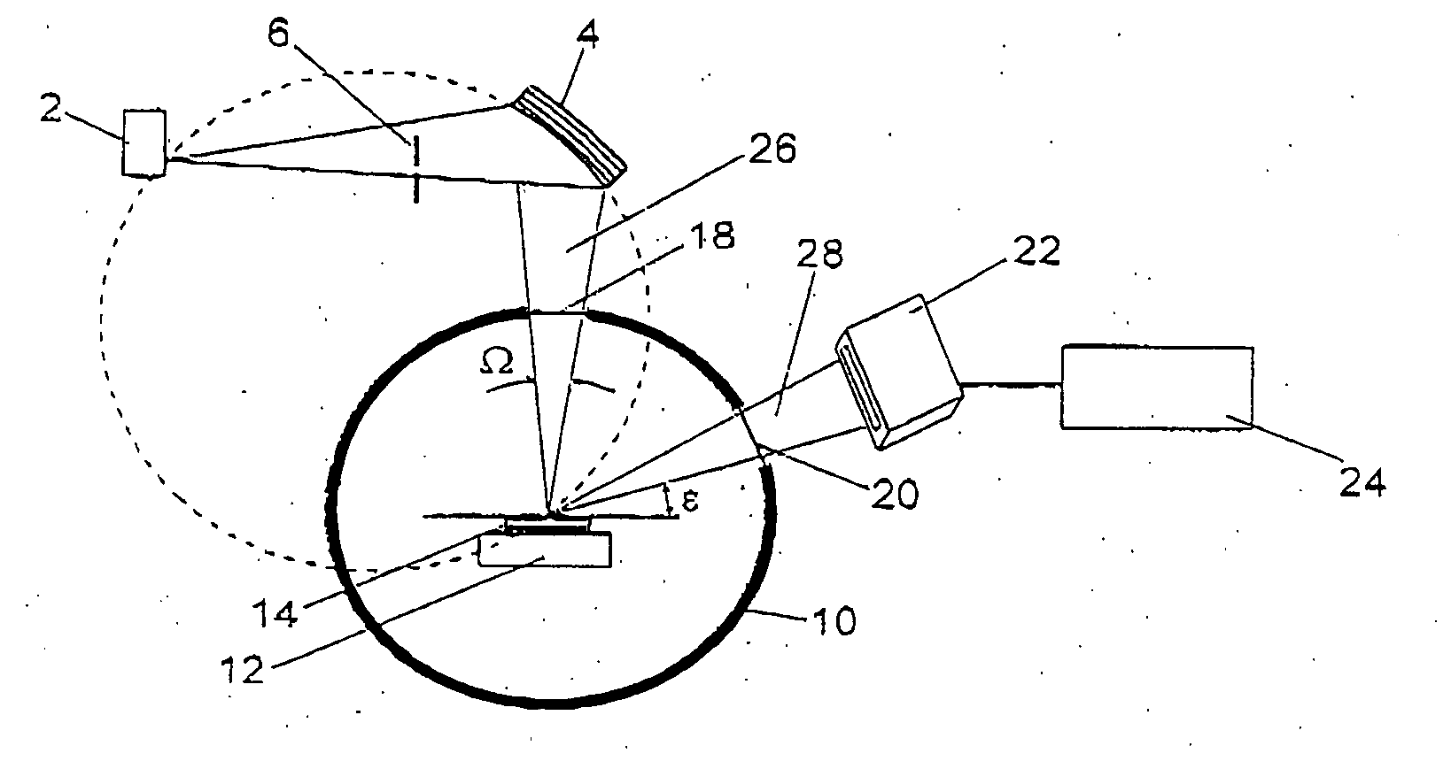
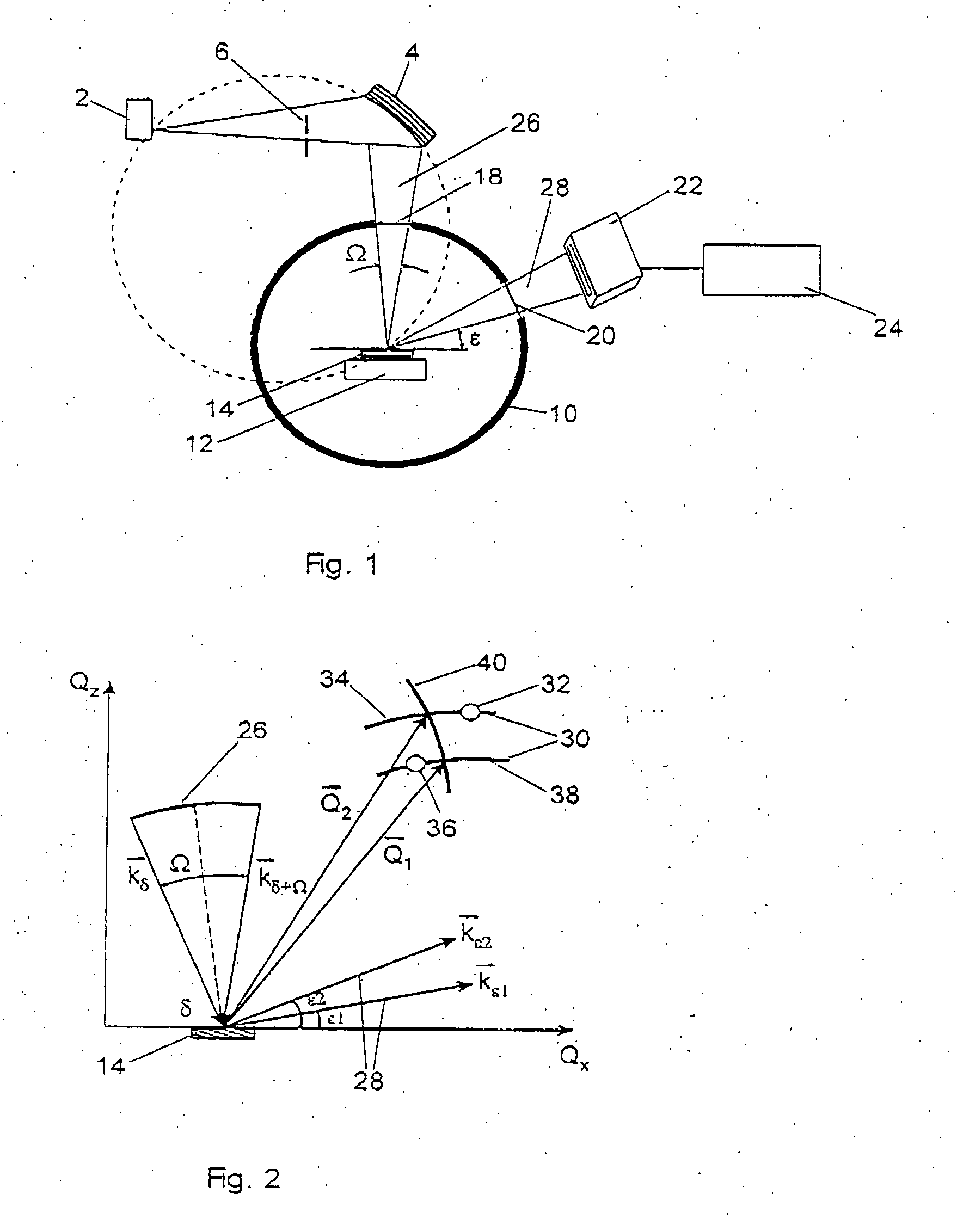
[0039] As shown in FIG. 1, in a preferred embodiment of the invention, a line source X-ray tube 2, the line extending in to the plane of the paper, is used to generate X-rays. A Johansson monochromator 4 is provided and a moveable slit 6 of adjustable size provided between the X-ray tube 2 and monochromator 4.

[0040] A growth chamber 10 has a sample stage 12 for mounting sample 14. The sample is rotated in this case by the gas flow used during growth. The growth chamber has an input window 18 for allowing X-rays from the monochromator 4 to reach the sample stage and an output window 20. In the specific example the input and exit windows are of beryllium. The windows are sealed.

[0041] A multichannel detector 22 is provided adjacent to the output window 20 for measuring X-rays passing through the output window 20. The multichannel detector 22 is connected to measurement electronics 24 for analysing the detected X-rays. The measurement electronics may contain a computer and calculatio...


PUM

PropertyMeasurementUnit
diffraction angleaaaaaaaaaa
timeaaaaaaaaaa

Abstract

A monochromator 4 is used to direct X-rays from X-ray source 2 onto a sample 14 as a convergent beam. The sample 14 is in a growth chamber. The sample is rotated, and diffraction measurements are made in parallel with multichannel detector 22. A specific reflection is used so that the intensity against angle graph measured in the multichannel detector gives information about the vertical lattice parameter. To compensate for wobble inevitably introduced by the rotation of the sample, short time measurements are made and summed.

Description

CROSS REFERENCE TO RELATED APPLICATIONS [0001] This application claims priority from European Patent Application Serial No. 04251181.6, entitled “Diffractometer,” filed on Mar. 1, 2004, which is hereby incorporated by reference, in its entirety. TECHNICAL FIELD [0002] The invention relates to a diffractometer and in particular to a diffractometer suitable for incorporation into a growth chamber, for example of a Metal-Organic Chemical Vapour Deposition (MOCVD) reactor, as well as to a growth chamber with the diffractometer installed, and methods of operating the diffractometer and processing data from the diffractometer. BACKGROUND ART [0003] MOCVD is a widely used process for depositing semiconductors and other materials in a growth chamber. It is very useful to monitor the growth of material in the growth chamber, and X-ray diffraction is a promising tool for this. There is also a need for monitoring growth in other types of growth chamber. [0004] However, the construction of grow...

Claims


Application Information

Patent Timeline
Patent Type & Authority Applications(United States)
IPC IPC(8): C30B25/16G01N23/207C30B35/00G01N23/20H01L21/205
CPCC30B25/16G01N23/20C30B35/00
Inventor LISCHKA, KLAUSKHARCHENKO, ALEXANDER
Owner PANALYTICAL BV
Why Eureka
Try Eureka