Heat transfer system for a mold

a heat transfer system and mold technology, applied in the field of heat transfer systems, can solve the problems of operator safety problems, molds have a tendency to heat up during use, and production delays,

Inactive Publication Date: 2005-09-08
FREMONT PLASTIC MOLDS
View PDF6 Cites 42 Cited by
  • Summary
  • Abstract
  • Description
  • Claims
  • Application Information

AI Technical Summary

Problems solved by technology

One drawback of any molding process is that a mold has a tendency to heat up during use due to one or more factors, including friction, pressure or heat transfer from other components in the molding machinery.
This undesired heat can cause production delays, safety issues to operators and potentially damage to the molds and molding machinery.
Further, the setting of

Method used


Image

  • Heat transfer system for a mold
  • Heat transfer system for a mold
  • Heat transfer system for a mold

Examples


first embodiment

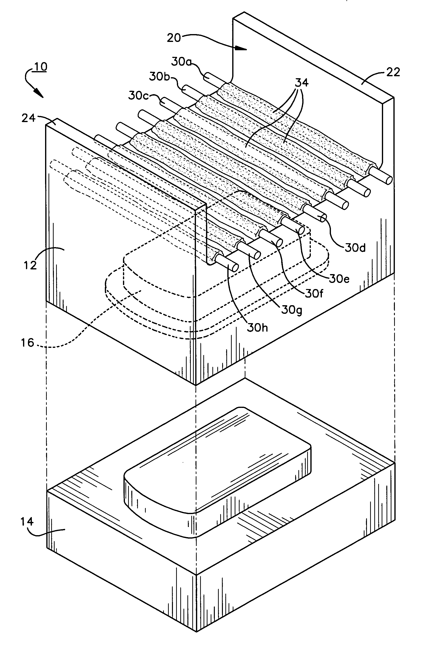
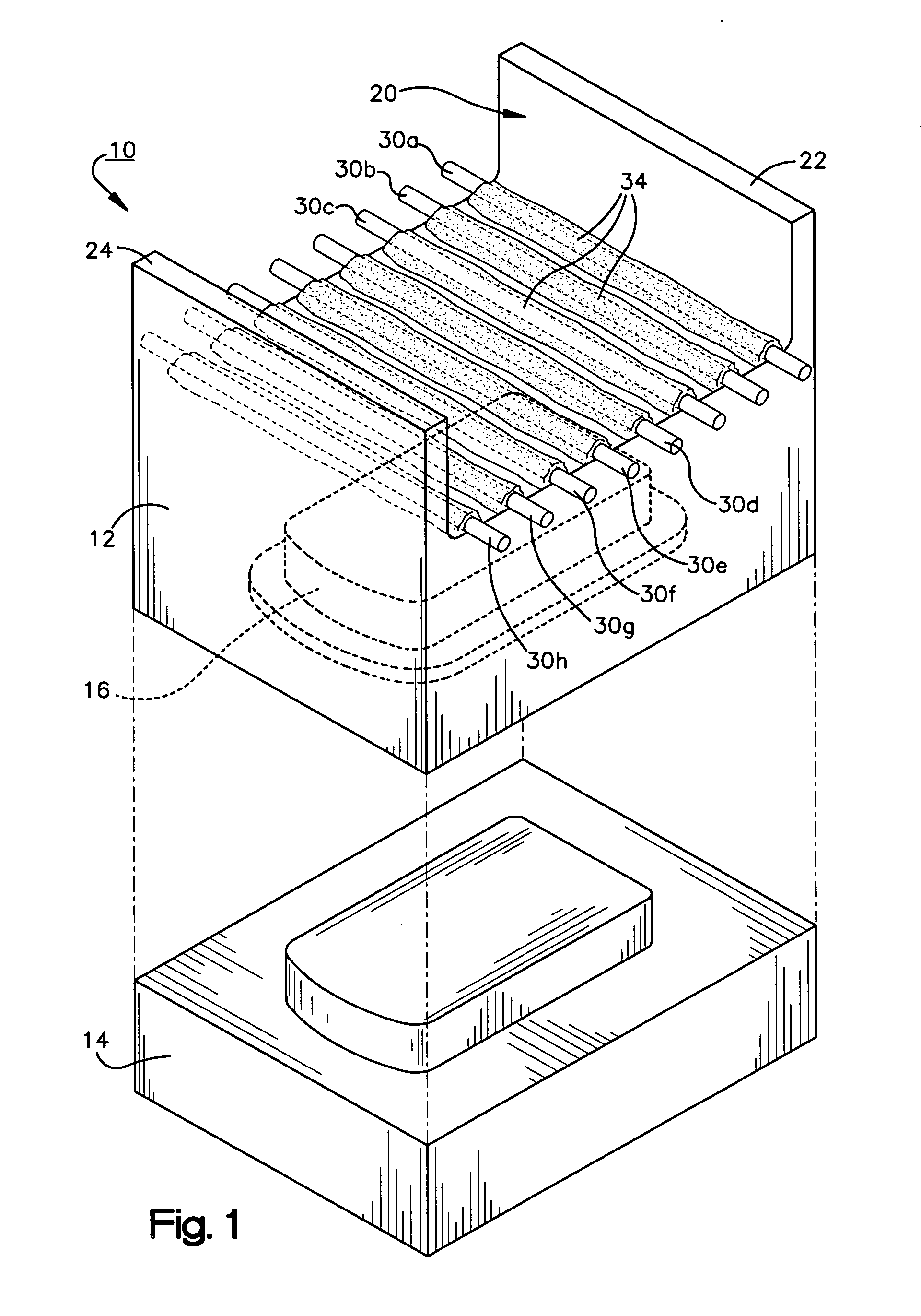
[0011]FIG. 1 is a perspective view of a mold assembly constructed according to the present invention;

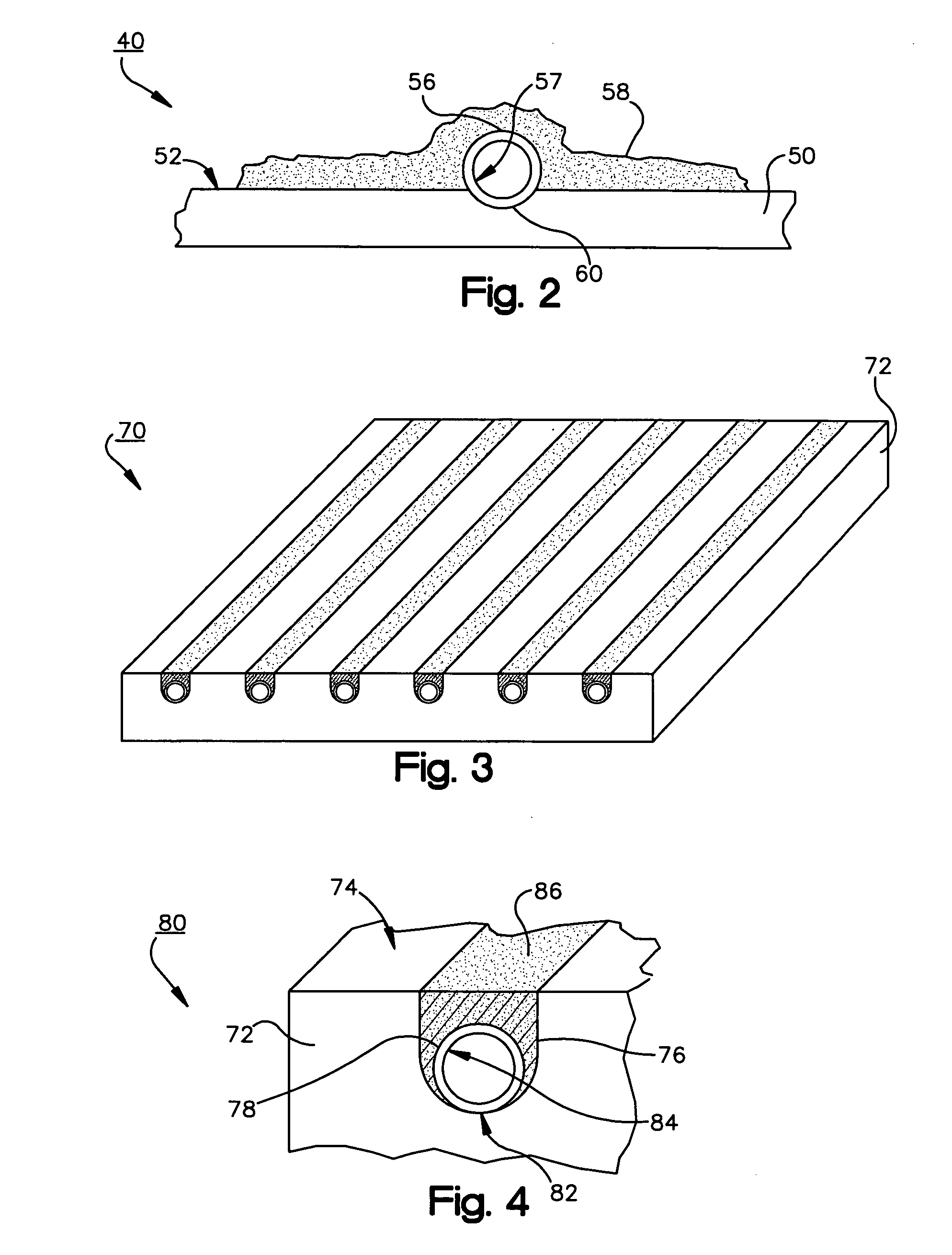
[0012]FIG. 2 is a cross-sectional fragmentary view of a portion of the mold assembly illustrated in FIG. 1, showing a tube rigidly attached to an external surface of a mold base;

second embodiment

[0013]FIG. 3 is a perspective view of an apparatus constructed according to the present invention;

[0014]FIG. 4 is a cross-sectional fragmentary view of a portion of the apparatus illustrated in FIG. 3, showing a tube rigidly attached within a channel defined by an external surface of a mold section;

[0015]FIG. 5 is a top view of a mold assembly constructed according to the first embodiment of the present invention, showing elongated hollow members running the length of the mold assembly; and

[0016]FIG. 6 is a cross-sectional view of the mold assembly of FIG. 5.


PUM

PropertyMeasurementUnit
Diameteraaaaaaaaaa
Lengthaaaaaaaaaa
Volumeaaaaaaaaaa

Abstract

An apparatus for facilitating heat transfer in a mold is disclosed. The apparatus includes a mold section having an external surface defining a concave-shaped channel, a hollow elongated member positioned within the channel, and a binding material attaching the hollow elongated member to the mold section. Heat transfers from the mold section to relatively cooler heat transfer fluid when the fluid is directed through the hollow elongated member. Heat may also transfer from the molded piece to the mold section when the fluid is transported through the hollow elongated member. The apparatus may have any number of channels and members. The hollow elongated member may be a copper tube and be completely or partially positioned within the channel. The mold section and binding material may be made of aluminum. A method of manufacture of the apparatus is also disclosed.

Description

FIELD OF THE INVENTION [0001] The present invention relates to a heat transfer system and more particularly to a heat transfer system for a mold having improved thermal and economic properties. BACKGROUND OF THE INVENTION [0002] Plastic molding is a process used to form substances into desired shapes. Typically, a plastic substance, in a fluid state, is placed into a mold by gravity or mechanical force. Most molds consist of two or more conjoined blocks, which are separated after the substance has solidified. The finished part is removed from the mold and the molding process is repeated. Certain post-mold process steps may be taken to finish the part. [0003] Plastics may be molded using a variety of processes including blow molding, injection molding, compression molding, transfer molding, rotational molding and extrusion. Blow molding is basically a bulging process. A tubular piece of plastic is heated and then pressurized internally and expanded into the cavity of a relatively coo...

Claims


Application Information

Patent Timeline
IPC IPC(8): B29C49/00
CPCB29C33/04B29C33/3828B29C45/7312B29C49/4823B29K2905/10
Inventor CASS, MARTINOVERMYER, SHAWNRAUBENOLT, BILL
Owner FREMONT PLASTIC MOLDS
Why Eureka
Try Eureka