Eureka AIR delivers breakthrough ideas for toughest innovation challenges, trusted by R&D personnel around the world.

Mixer circuit and receiver circuit using the same

Inactive Publication Date: 2005-09-08
PANASONIC CORP
View PDF34 Cites 9 Cited by
  • Summary
  • Abstract
  • Description
  • Claims
  • Application Information

AI Technical Summary

Benefits of technology

[0019] Accordingly, it is an object of the present invention to provide a mixer circuit and a receiver circuit, capable of suppressing a variation of the DC offset of the quadrature demodulator between during a normal operation and during a DC offset correction, to thereby perform an accurate DC offset correction without increasing the circuit scale or the number of peripheral parts, as well as a method of DC offset correction to be performed in such circuit.
[0021] In the circuit thus configured, the bypass circuit, including the second differential amplifier having a pair of differential input terminals short-circuited with each other, and provided in parallel with the first differential amplifier, inactivates the first differential amplifier and activates the second differential amplifier during a DC offset correction. Accordingly, the quadrature demodulator can operate under unchanged conditions and without receiving a signal input, during the DC offset correction. This results in suppressing a variation of the DC offset of the quadrature demodulator between during a normal operation and during a DC offset correction, and thus performing an accurate DC offset correction. Besides, since all that is necessary is adding the second differential amplifier, the variation of the DC offset of the quadrature demodulator between during a normal operation and during a DC offset correction can be suppressed without increasing the circuit scale or the number of peripheral parts.
[0023] In the circuit thus configured, the bypass circuit, including the second differential amplifier having a pair of differential input terminals short-circuited with each other, and provided in parallel with the first differential amplifier, inactivates the first differential amplifier and activates the second differential amplifier during a DC offset correction. Accordingly, the quadrature demodulator can operate under unchanged conditions and without receiving a signal input, during the DC offset correction. This results in suppressing a variation of the DC offset of the quadrature demodulator between during a normal operation and during a DC offset correction, and thus performing an accurate DC offset correction. Besides, since all that is necessary is adding the second differential amplifier, the variation of the DC offset of the quadrature demodulator between during a normal operation and during a DC offset correction can be suppressed without increasing the circuit scale or the number of peripheral parts.
[0030] By the first and the second method thus arranged, the mixer circuit or the receiver circuit provided with the bypass circuit including the second differential amplifier is employed, such that the first differential amplifier is inactivated while the second differential amplifier is activated, and the DC offset is detected and corrected under such state. Such method allows suppressing a variation of the DC offset of the quadrature demodulator between during a normal operation and during a DC offset correction, to thereby perform an accurate DC offset correction without increasing the circuit scale or the number of peripheral parts.
[0031] As described above, the mixer circuit and the receiver circuit, as well as the method of correcting the DC offset, allow suppressing a variation of the DC offset of the quadrature demodulator between during a normal operation and during a DC offset correction, to thereby perform an accurate DC offset correction without increasing the circuit scale or the number of peripheral parts.

Problems solved by technology

This leads to a drawback that a DC offset generated in the quadrature demodulator and the baseband amplifier has to be corrected, so as to prevent the saturation of the amplifier.
Especially in the direct conversion receiver circuit, since the amplification factor in the baseband range is large, the circuit becomes saturated with the DC offset and unable to operate normally, unless the DC offset is corrected.
Accordingly, the DC offset remains as it is when an input is not received, thus resulting in an erroneous DC offset correction.
However, providing a dummy high frequency amplifier incurs a disadvantage of an increase in circuit scale as well as in the number of peripheral parts.

Method used


Image

  • Mixer circuit and receiver circuit using the same
  • Mixer circuit and receiver circuit using the same
  • Mixer circuit and receiver circuit using the same

Examples


first embodiment

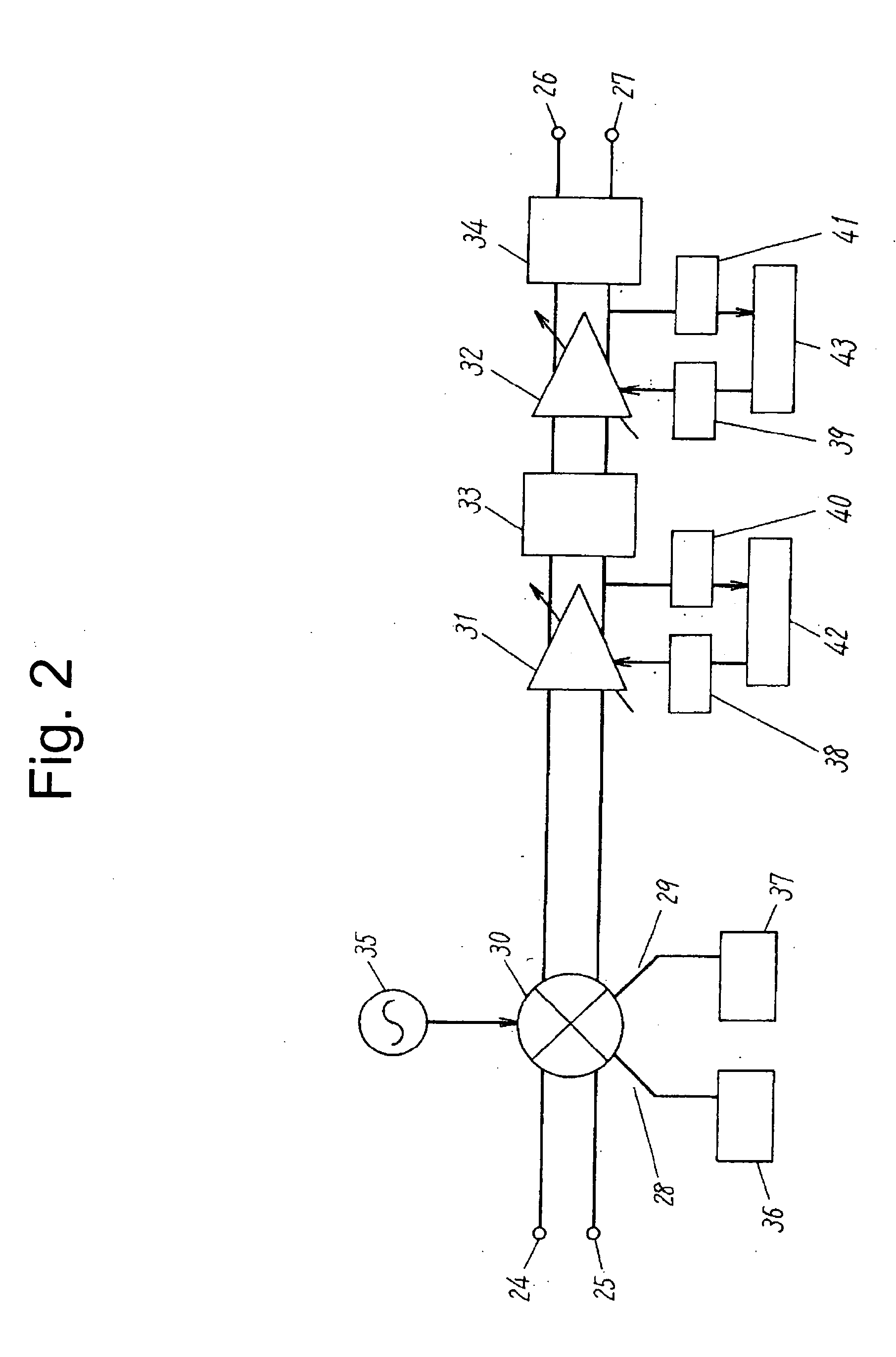
[0035] Referring to the drawings, a receiver circuit according to a first embodiment of the present invention will be described hereunder.

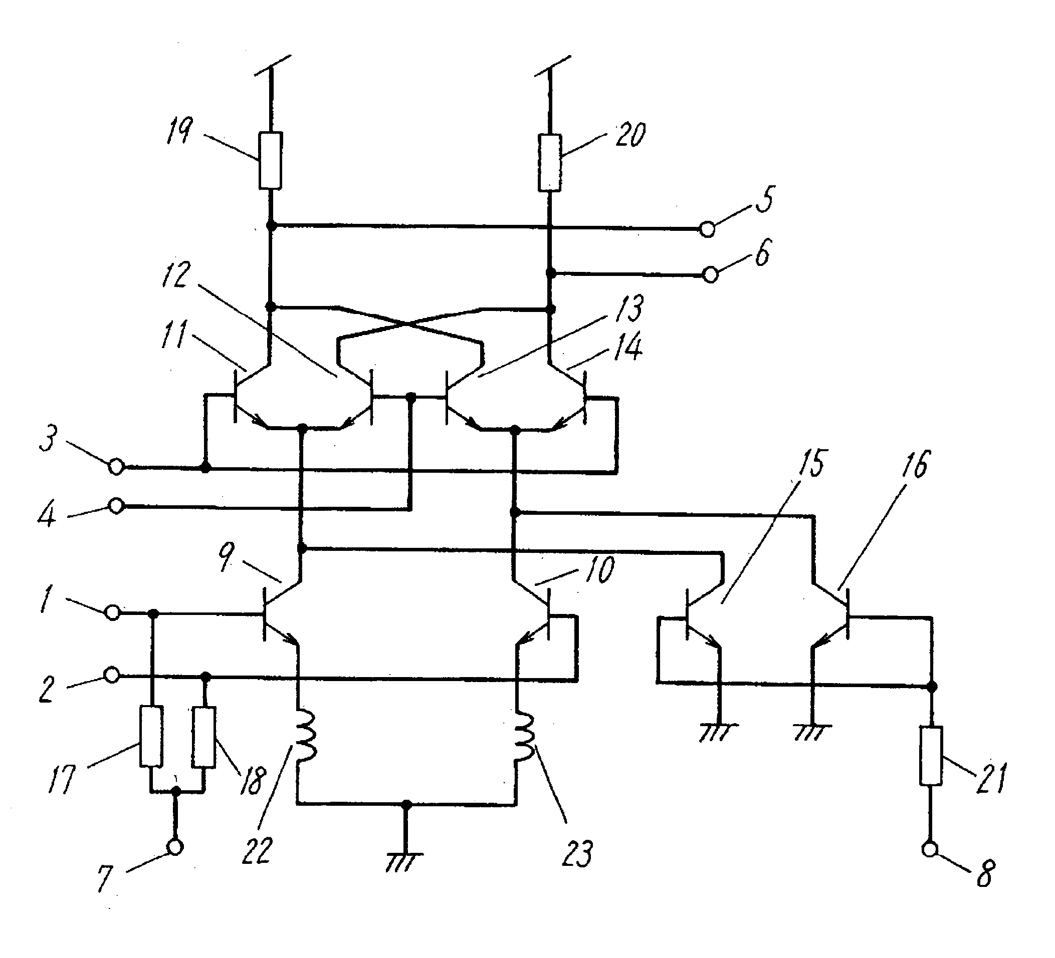
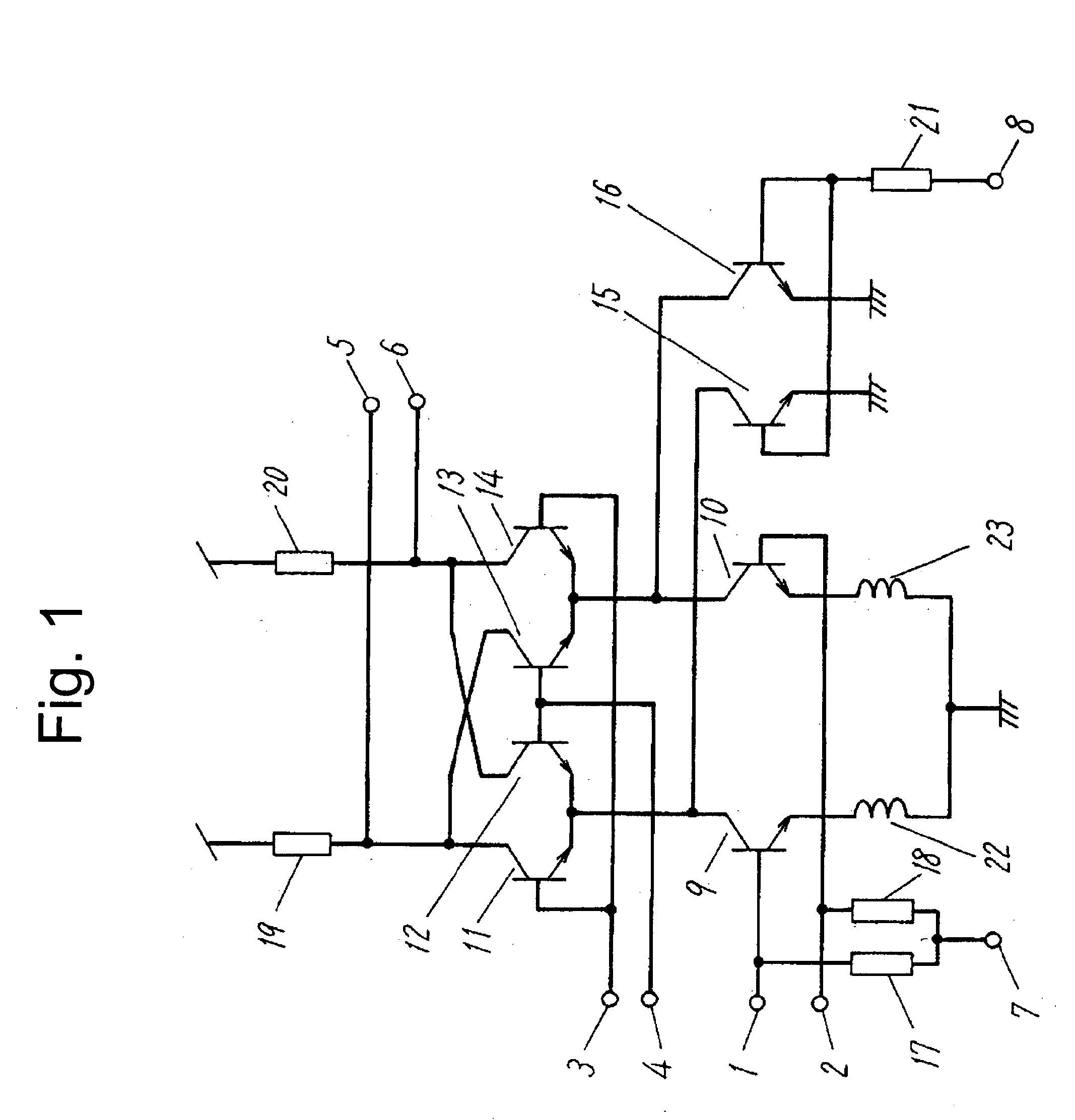
[0036]FIG. 1 is a circuit diagram showing a configuration of the mixer circuit according to the first embodiment of the present invention. The mixer circuit includes a quadrature demodulator constituted of a Gilbert cell, and a bypass circuit. A high frequency signal is input via a high frequency signal input terminal 1 and a negative-phase high frequency signal input terminal 2. The high frequency signal is amplified by a differential amplifier including a first transistor 9 and a second transistor 10. A first inductor 22 and a second inductor 23 are located between emitters of the first transistor 9 and the second transistor 10, to determine a gain.

[0037] The high frequency signal amplified by the differential amplifier is input to a switching circuit including a third transistor 11, a fourth transistor 12, a fifth transistor 13 and a sixth tr...


PUM


Abstract

A mixer circuit is provided with a quadrature demodulator including a Gilbert cell in which a first differential amplifier and a switching circuit are vertically stacked for connection and a bypass circuit including a second differential amplifier having a pair of differential input terminals short-circuited with each other, and provided in parallel with the first differential amplifier. Correction of a DC offset is performed by inactivating the first differential amplifier and activating the second differential amplifier, and detecting the DC offset under such state.

Description

BACKGROUND OF THE INVENTION [0001] 1. Field of the Invention [0002] The present invention relates to a direct conversion receiver circuit, and to a mixer circuit to be used therein. The mixer circuit includes a quadrature demodulator constituted of a Gilbert cell. The present invention also relates to a method of correcting a DC offset utilizing the receiver circuit or mixer circuit. To be more specific, the present invention relates to a circuit configuration of the receiver circuit or the mixer circuit, and a method of correcting a DC offset therein, that can suppress a variation of the DC offset of the quadrature demodulator between during a normal operating and during a DC offset correction. [0003] 2. Prior Art [0004] The recent reduction in size of mobile phones has urged the development of a direct conversion integrated receiver circuit, which can save the number of peripheral devices such as a filter. Under the direct conversion system, a high frequency signal is directly con...

Claims


Application Information

Patent Timeline
IPC IPC(8): H03D7/14
CPCH03D7/1425H03D7/1433H03D2200/0047H03D7/165H03D2200/0043H03D7/1458
Inventor HAMASAKI, TOSHINORIISHIDA, KAORU
Owner PANASONIC CORP
Why Eureka
Eureka Blog
Learn More