Self tying shoe

a self-tying and shoe technology, applied in the field of shoes, can solve the problem of adding undue complexity to shoes

Inactive Publication Date: 2005-09-15
LABBE FREDERICK
View PDF6 Cites 144 Cited by
  • Summary
  • Abstract
  • Description
  • Claims
  • Application Information

AI Technical Summary

Benefits of technology

[0016] To provide for fast simple tying and untying of shoe laces.

Problems solved by technology

Some inventions are concerned with maintaining a proper tension to the laces while other systems use straps as means for tying the shoe, the latter being rather restrictive since it limits the outer design choices of the shoe since because of the proprietary straps.
Still another system involves the use of pneumatic means which adds undue complexity to the shoes.

Method used


Image

  • Self tying shoe
  • Self tying shoe
  • Self tying shoe

Examples


Embodiment Construction

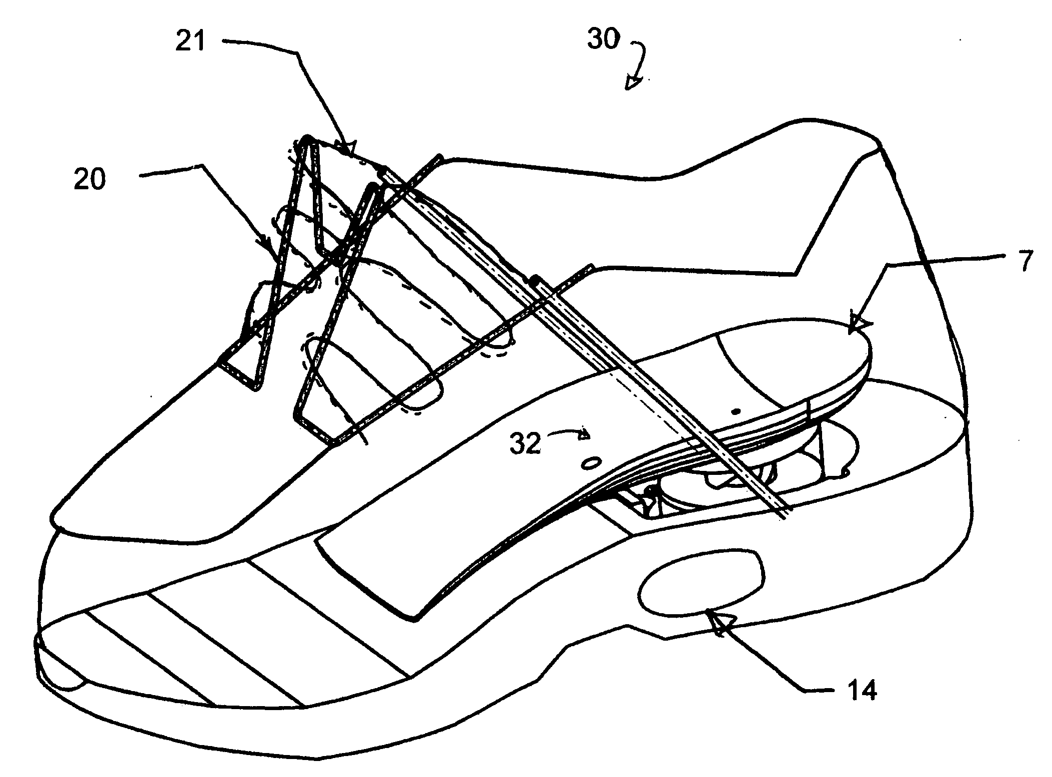
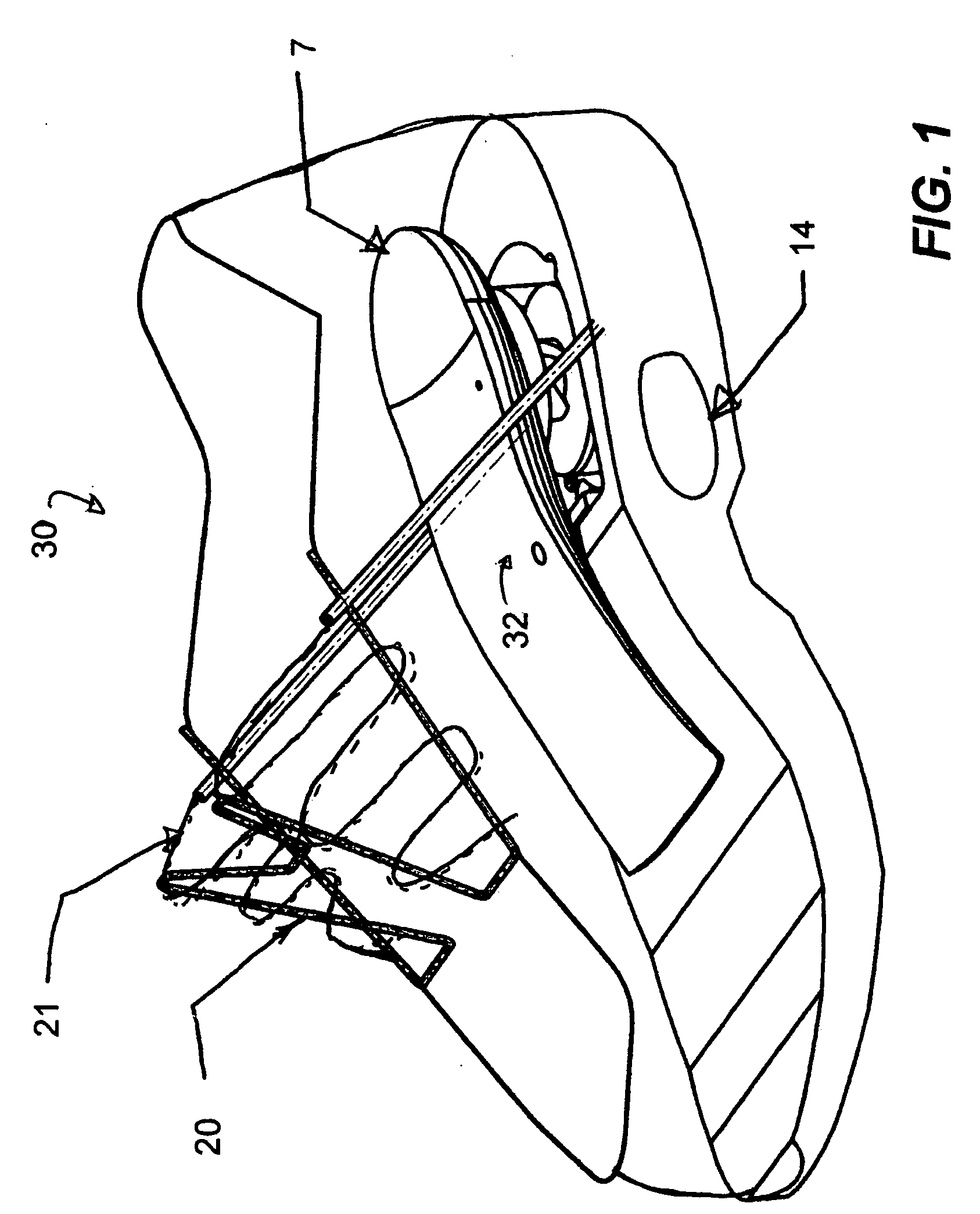
[0023]FIG. 1 See through isometric view of the shoe unlaced with the inner sole in an upward position.

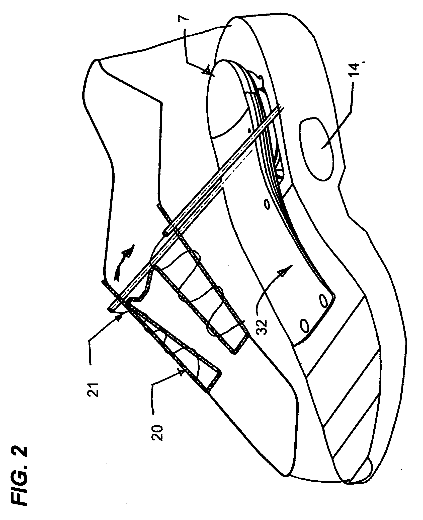
[0024]FIG. 2 See through isometric view of the shoe laced with the inner sole in a downward position.

[0025]FIG. 3 Isometric view of the interior mechanism with the inner sole in an upward position.

[0026]FIG. 4 Isometric view of the interior mechanism with the inner sole in a downward position.

[0027]FIG. 5 See through side elevation with the inner sole in a downward position.

[0028]FIG. 6 See through side elevation with the inner sole in an upward position.

[0029]FIG. 7 Exploded view of the interior mechanism.

[0030]FIG. 7bc Side cutaway detail of the peg and sleeve showing the open and closed positions respectively

DETAILED DESCRIPTION OF THE PREFERRED EMBODIMENT

[0031]FIG. 1 A self tying shoe (30) has an interior mechanism (32) which consists of visible elements such as an inner sole (7) hingedly attached to a base (1) set inside the shoe (30). in this illustration, the inner s...


PUM


Abstract

A self tying shoe wherein the weight of a user who, upon sliding his foot inside the shoe will depress a hingedly movable inner sole which actuates a mechanism which pulls on the laces so as to close in the tongue of the shoe towards the user's foot, thus lacing the shoe. The user can simply pump the inner sole or walk a couple of steps to accomplish the lacing of the shoes. Using his other foot, the user can move a knob in either one of two positions, one being for tying and the other being for untying the shoe. Most of the mechanical components are situated underneath the movable inner sole and are interconnected in a way reminiscent of the cooperating interconnections of clockwork.

Description

BACKGROUND OF THE INVENTION [0001] 1. Field of the invention [0002] The invention relates generally to footwear but more particularly to a system for tying down shoes. [0003] 2. Background of the Invention [0004] Lacing shoes is boring business and several inventors have tried over the years to simplify the matter. [0005] U.S. Pat. No. 4,741,115 shows a ski boot with an operating assembly for the closing and adjustment and comprises a power source supported by the ski boot and operating a driving gearwheel which is selectively engageable with driven gearwheels for the winding of cables of closing and / or adjustment devices of the boot. [0006] U.S. Pat. No. 5,205,055 shows a shoe member including a plurality of securement webs directed about a lacing gap within the shoe upper, wherein the webs are each mounted slidably within associated cavities, with tether lines mounted to the webs operative above a crank pulley, with the crank pulley in operative engagement with a slidable actuator...

Claims


Application Information

Patent Timeline
Patent Type & Authority Applications(United States)
IPC IPC(8): A43C11/00
CPCA43B11/00A43C11/165A43C11/14A43C11/008A43C11/00
Inventor LABBE, FREDERICK
Owner LABBE FREDERICK
Why Eureka
Try Eureka