Thermal conversion device and process

a conversion device and heat exchange technology, applied in steam engine plants, engines without rotary main shafts, catalytic cracking, etc., can solve the problems of weak sunlight energy source, difficult to effectively use sunlight for home energy needs, and difficult to harness sunlight efficiently for conversion into useful forms of energy

Active Publication Date: 2005-09-15
MARNOCH IAN A
View PDF30 Cites 42 Cited by
  • Summary
  • Abstract
  • Description
  • Claims
  • Application Information

AI Technical Summary

Benefits of technology

[0015] a plurality of cooperating valves for alternately regulating a flow of thermal conducting fluid from the first and second thermal sources to the first and second vessels, the plurality of cooperating valves alternating between first and second operating positions, the plurality of cooperating valves permitting a flow of thermal conducting fluid from the first thermal source to the first vessel and from the second thermal source to the second vessel in first operating position, the plurality of cooperating valves preventing a flow of thermal conducting fluid from the first thermal source to the second vessel and from the second thermal source to the first vessel in the first operating position, the plurality of cooperating valves permitting a flow of thermal conducting fluid from the first thermal source to the second vessel and from the second thermal source to the first vessel in the second operating position, the plurality of cooperating valves preventing a flow of thermal conducting fluid from the first thermal source to the first vessel and from the second thermal source to the second vessel in the second operating position;
[0020] delivering the thermal transfer fluid from the first thermal source to the first vessel thereby raising the pressure of the gas in the first vessel;
[0021] delivering the thermal transfer fluid from the second thermal source to the second vessel thereby lowering the pressure of the gas in the second vessel;
[0022] delivering gas under pressure from the first vessel to a pressure activated actuator and applying suction from the second vessel to the pressure activated actuator thereby causing the pressure activated actuator to move in a first direction.

Problems solved by technology

However, sunlight is a weak energy source compared to traditional energy sources such as fossil fuels.
It is very difficult to harness sunlight efficiently for conversion into useful forms of energy.
It is particularly difficult to use sunlight effectively for home energy needs.
However, this conversion is inefficient and high in cost.
Also, some types of photovoltaic solar cells contain mercury that is highly toxic.
Other renewable energy sources have the drawback of being environmentally unfriendly.
For example, wind power plants can damage local animal populations.
Also, hydroelectric dams can cause problems such as the creation of large reservoirs.
This can upset the ecological balance of the surrounding environment.
This has the consequences of disrupting local animal populations and their migration patterns.
Dams also affect fish populations.
These methods have the drawback of failing to obtain a sufficient concentration of heat to activate the process in an efficient manner.
Such methods to date have failed to produce an economically viable energy generation process.
This has not yielded an economically viable method for energy production.

Method used


Image

  • Thermal conversion device and process
  • Thermal conversion device and process
  • Thermal conversion device and process

Examples


Embodiment Construction

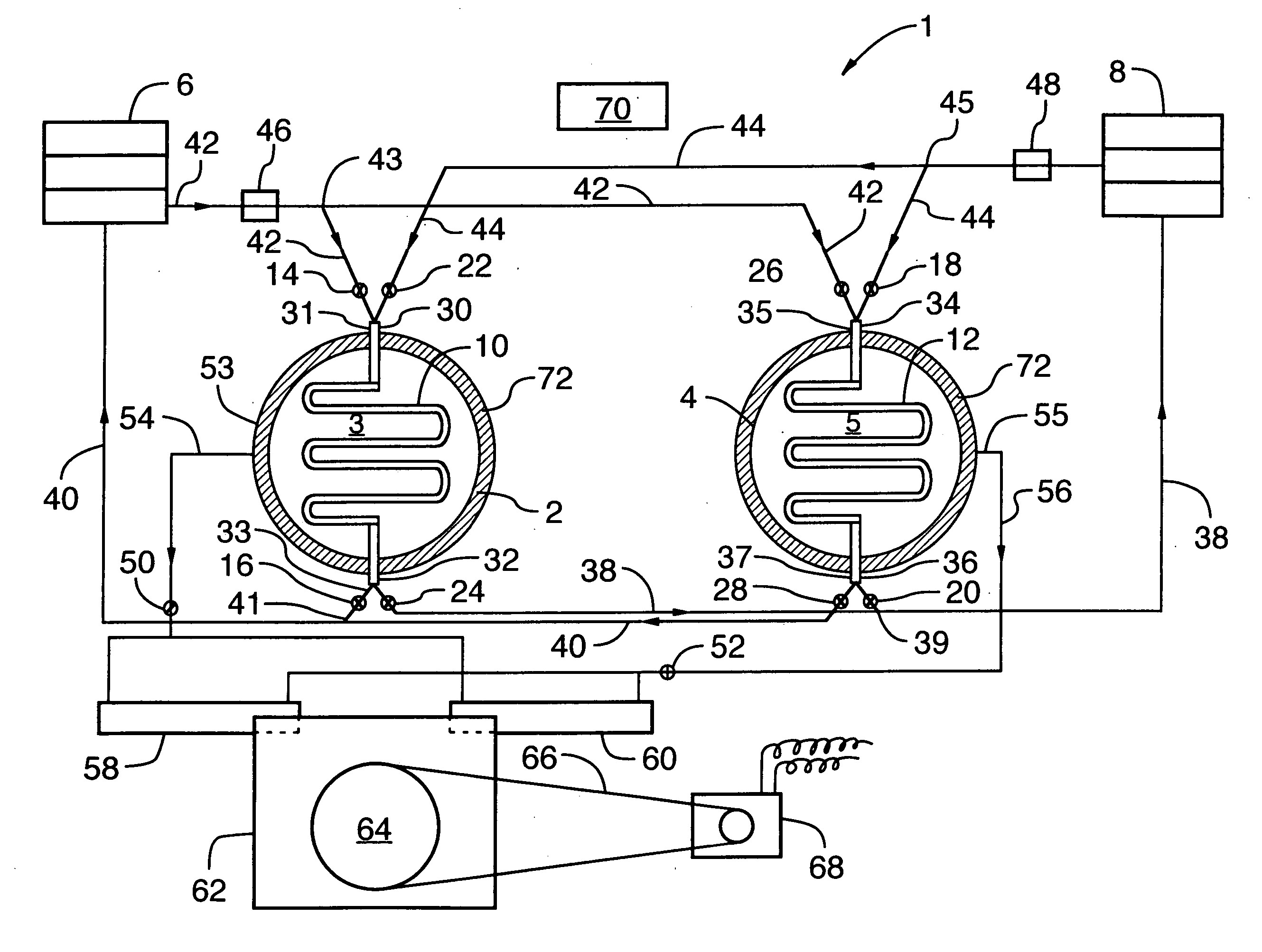
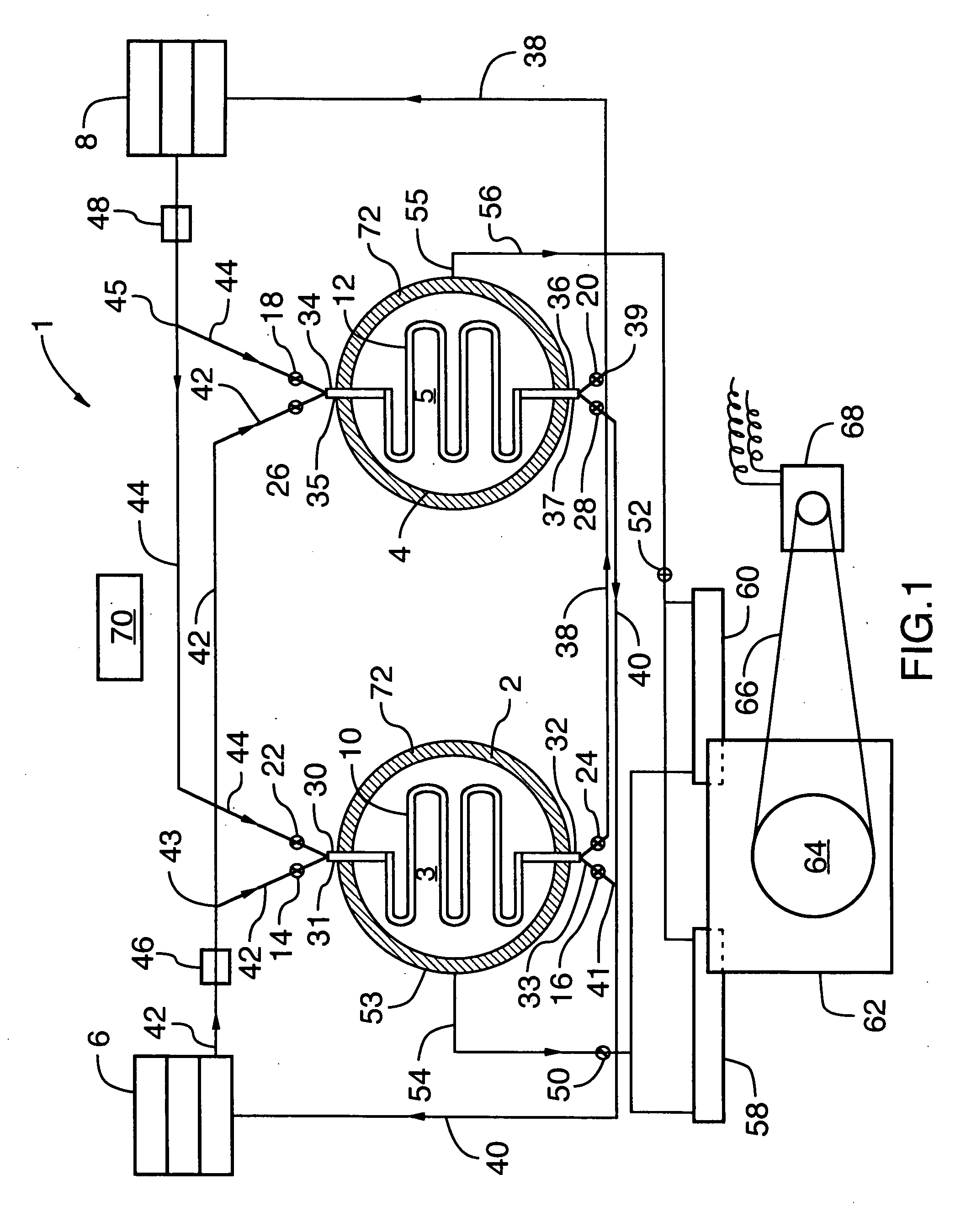
[0033] The present invention provides an apparatus for converting a differential in thermal energy between two thermal sources into mechanical energy that can be used for a wide range of applications known to a person skilled in the art including the generation and storage of electrical energy. The invention also relates to a method of converting a differential in thermal energy between two thermal sources into mechanical energy. The method can be carried out with the apparatus of the present invention.

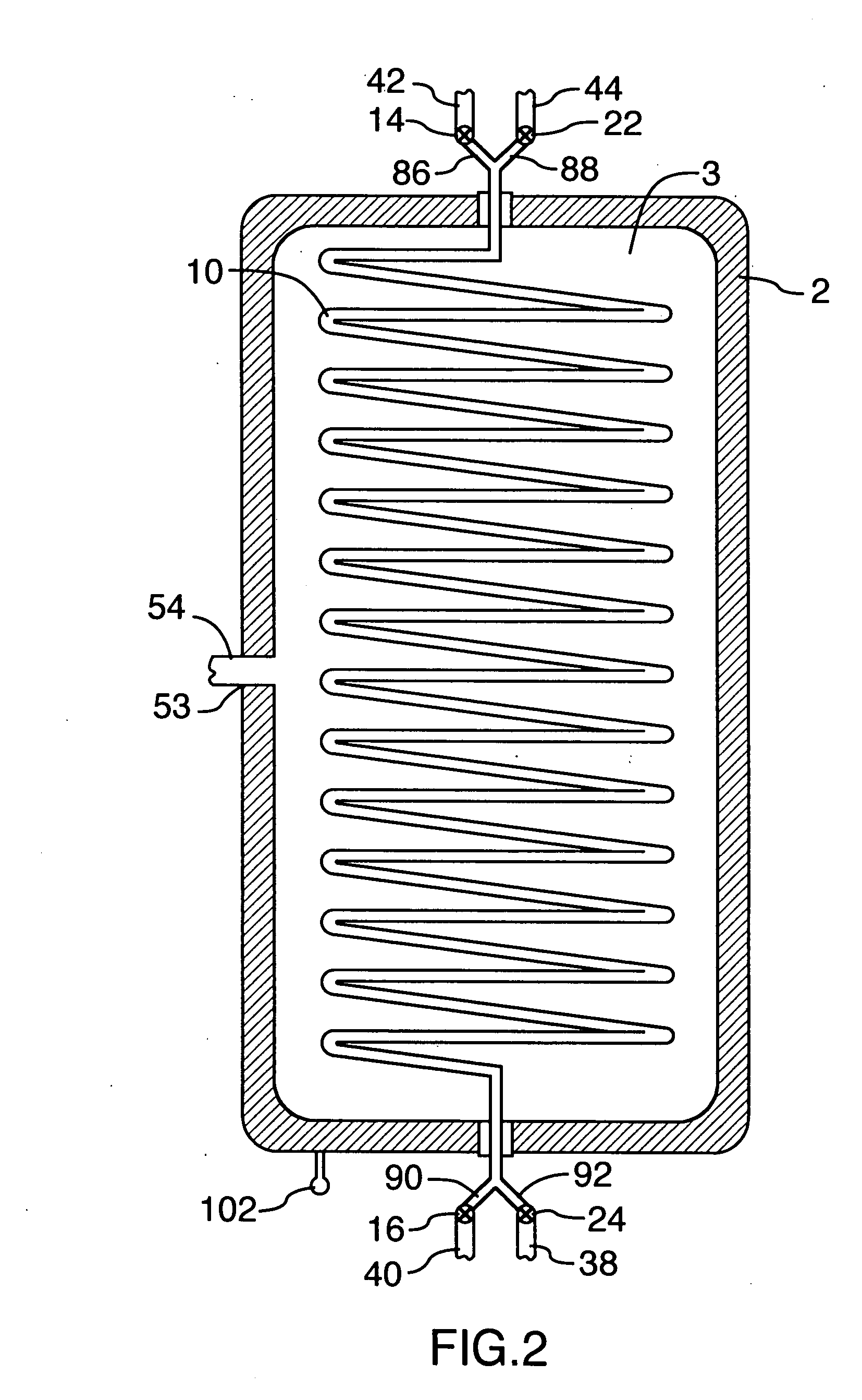
[0034] A preferred embodiment of the present is shown in FIG. 1. Apparatus 1 includes a first vessel 2 and a second vessel 4. Each of the two vessels is preferably a sealed container that defines a chamber therein for containing a gas under pressure. As shown in FIGS. 2 and 3, the first vessel 2 defines a chamber 3 and the second vessel 4 defines a chamber 5. The vessels contain the gas under pressure in the chambers. The vessels are shown in lateral cross section in FIG. 1 and in lo...


PUM

PropertyMeasurementUnit
diameteraaaaaaaaaa
diameteraaaaaaaaaa
thermal energyaaaaaaaaaa

Abstract

An apparatus and method for converting a differential in thermal energy between a first thermal source having a thermal conducting fluid and a second thermal source having a thermal conducting fluid is provided. The apparatus emplys a first vessel and a second vessel. Each of the vessels contain a gas under pressure The vessels contain heat exchanging coils that are connected to the thermal sources by fluid lines. A plurality of cooperating valves regulate the flow of the thermal conducting fluid from the first and second thermal sources to the first and second vessels. The valves alternate between first and second operating positions. In the first position, the valves permit a flow of thermal conducting fluid from the first thermal source to the first vessel and from the second thermal source to the second vessel and prevent a flow of thermal conducting fluid from the first thermal source to the second vessel and from the second thermal source to the first vessel. In the second position, the valves permit a flow of thermal conducting fluid from the first thermal source to the second vessel and from the second thermal source to the first vessel and prevent a flow of thermal energy from the first thermal source to the first vessel and from the second thermal source to the second vessel. A pressure driven actuator in fluid communication with the first and second vessels is driven into reciprocating motion between a first position and a second position by alternating positive pressure and negative pressure from the first and second vessels.

Description

FIELD OF THE INVENTION [0001] The invention relates to devices and methods for converting thermal energy into kinetic energy especially for the production and / or storage of electrical energy. BACKGROUND OF THE INVENTION [0002] Given society's ever increasing energy consumption, there is a resultant high demand for energy. Since the earth's natural energy reserves are becoming depleted and prices of oil and natural gas are relatively high, there is a demand for new sources of energy. [0003] There have been attempts to convert existing forms of energy into forms of energy that can be used to satisfy our energy needs. Many of these processes harness energy sources that are replenished by natural processes. These energy sources are referred to as renewable energy sources. An example is solar energy where energy from the sun in the form of heat energy and light energy is converted into electrical energy. However, sunlight is a weak energy source compared to traditional energy sources suc...

Claims


Application Information

Patent Timeline
Patent Type & Authority Applications(United States)
IPC IPC(8): C10G11/00F01B11/00F01B23/10F01K13/00F01K25/00F01K27/00F03G7/06
CPCF01K3/12
Inventor MARNOCH, IAN A.
Owner MARNOCH IAN A
Why Eureka
Try Eureka