Logging-while-coring method and apparatus

Inactive Publication Date: 2005-09-15
THE TRUSTEES OF COLUMBIA UNIV IN THE CITY OF NEW YORK
View PDF12 Cites 47 Cited by
  • Summary
  • Abstract
  • Description
  • Claims
  • Application Information

AI Technical Summary

Benefits of technology

[0014] A new logging-while-coring technology is proposed. A primary object of the present invention is the reduction of time required to log after drilling and coring has been completed in a hole. Another object of the present invention is to make in situ mea

Problems solved by technology

Until now it has not been possible to continuously collect large diameter core and in situ logging data simultaneously.
Continuous wireline-retrievable coring, for example, is routine in nearly all Ocean Drilling program (ODP) drill holes, whereas industry coring programs are often limited in key intervals due to time and cost constraints.
The above described method is time consuming because it requires two separate drill holes: a first hole for obtaining core samples and a second hole for obtaining logging-while-drilling data.

Method used


Image

  • Logging-while-coring method and apparatus
  • Logging-while-coring method and apparatus
  • Logging-while-coring method and apparatus

Examples


Embodiment Construction

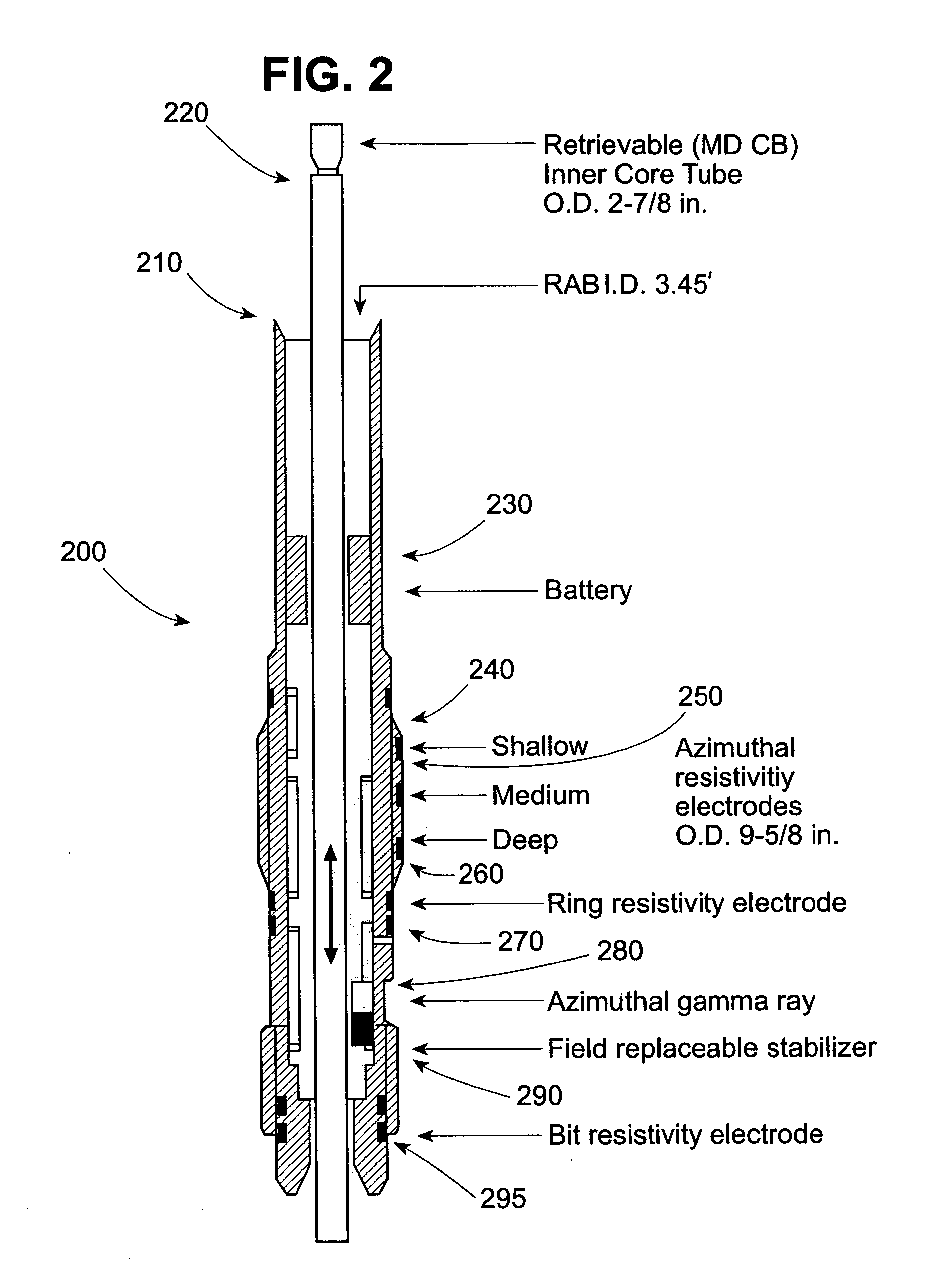
[0053] The present invention combines a coring system with logging-while-drilling system, both of which are known in the art.

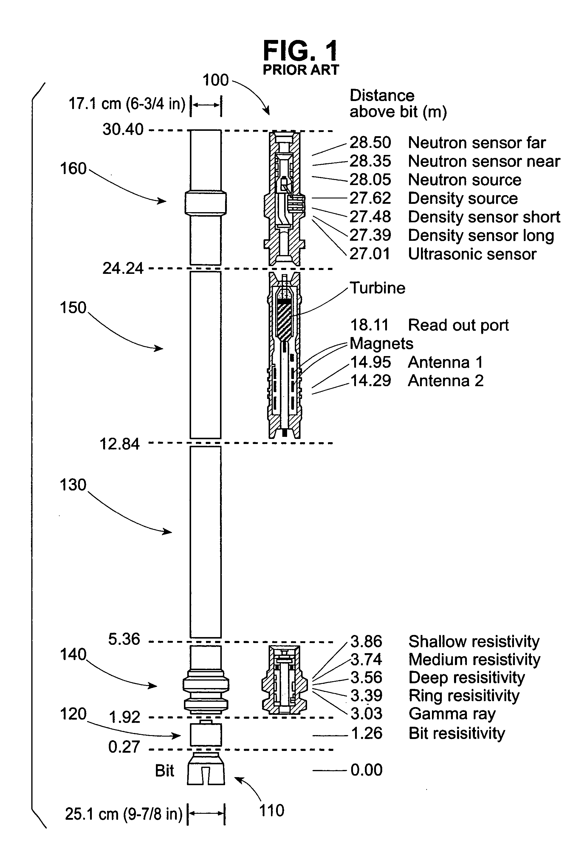
[0054] A schematic of the prior art is depicted in FIG. 1. FIG. 1 illustrates a logging-while-drilling downhole assembly 100. The logging-while-drilling downhole assembly 100 includes a bit 110, a bit sub 120, a measurement-while-drilling section 130, a logging-while-drilling lower sub-assembly 140, a mechanically-rotatable-turbine section 150, and a logging-while-drilling upper sub-assembly 160.

[0055] Bit 110 is comprised of three rotatable heads that break up rock when a force is applied to the logging-while-drilling downhole assembly 100. Bit sub 120 is a pipe sub-assembly that couples the bit 110 to the rest of the logging-while-drilling downhole assembly 100.

[0056] Measurement-while-drilling (MWD) section 130 performs measurements such as sensing ambient pressure and weight on bit 110. Logging-while-drilling lower assembly 140 performs logging measurem...


PUM


Abstract

A method and apparatus for downhole coring while receiving logging-while-drilling tool data. The apparatus includes core collar and a retrievable core barrel. The retrievable core barrel receives core from a borehole which is sent to the surface for analysis via wireline and latching tool The core collar includes logging-while-drilling tools for the simultaneous measurement of formation properties during the core excavation process. Examples of logging-while-drilling tools include nuclear sensors, resistivity sensors, gamma ray sensors, and bit resistivity sensors. The disclosed method allows for precise core-log depth calibration and core orientation within a single borehole, and without at pipe trip, providing both time saving and unique scientific advantages.

Description

CROSS-REFERENCE TO RELATED APPLICATIONS [0001] This application claims priority under 35 U.S.C. §119(e) to U.S. Provisional Apl. Ser. No. 60 / 499,265, filed on Aug. 29, 2003, entitled SYSTEM FOR PERFORMING DOWNHOLE LOGGING WHILE CORING, which is expressly incorporated herein by reference in its entirety.STATEMENT AS TO FEDERALLY SPONSORED RESEARCH OF DEVELOPMENT [0002] The invention described herein was made at least in part with U.S. government support under Contract No. JSC 2-94, which was awarded by the U.S. National Science Foundation to Joint Ocean Institutions, Inc. and subcontracted to the assignee and under Contract No. JSC 2-06, which was awarded by the U.S. Department of Energy to Joint Ocean Institutions, Inc. and subcontracted to the assignee. Accordingly, the government may have certain rights in the subject invention.BACKGROUND [0003] 1. Technical Field [0004] The invention relates generally to a method and apparatus for wellbore coring and logging. More particularly, t...

Claims


Application Information

Patent Timeline
IPC IPC(8): E21B25/02E21B47/00E21B47/01
CPCE21B47/01E21B25/02E21B47/18
Inventor GOLDBERG, DAVID S.MYERS, GREGORY J.
Owner THE TRUSTEES OF COLUMBIA UNIV IN THE CITY OF NEW YORK
Why Eureka
Try Eureka