Eureka AIR delivers breakthrough ideas for toughest innovation challenges, trusted by R&D personnel around the world.

Transport of bulk material items

a technology of bulk material items and rotors, which is applied in the direction of conveyors, conveyors, jigging conveyors, etc., can solve the problems of unreliable oscillation of the machine table, more problems for spindles with rotors, etc., and achieve the effect of increasing the speed and acceleration of bulk material items and positive effects for the practical cours

Inactive Publication Date: 2005-09-15
BUCHI FELIX
View PDF6 Cites 19 Cited by
  • Summary
  • Abstract
  • Description
  • Claims
  • Application Information

AI Technical Summary

Benefits of technology

[0018] A sensor for measuring the deflection and frequency of the oscillating conveyor arm is expediently arranged therebelow. From the measured values which are determined, the processor can calculate the inherent frequency of the oscillating conveyor arm with the components fastened thereto, and the amplitude for each position on the oscillating conveyor surface, and evaluate them for industrial processes. The inherent frequency of the oscillation in the z-direction is also influenced by the design of weakening grooves and / or holes in the desired bending region. The energy required to generate an oscillating motion can thus be reduced and the process be made more efficient than in a frequency other than the inherent frequency which is basically also possible.
[0036] The device can be easily and automatically emptied of all bulk material items for the purpose of adaptation to another product or cleaning of the device.

Problems solved by technology

In larger systems, an oscillating conveyor arm which is movable in the x- or x- and y-direction could lead to unreliable oscillations of the machine table because of the larger mass.
Because of the rapid working cycle in fractions of seconds, spindles with a rotor would be more problematic, for example.

Method used


Image

  • Transport of bulk material items
  • Transport of bulk material items
  • Transport of bulk material items

Examples


Embodiment Construction

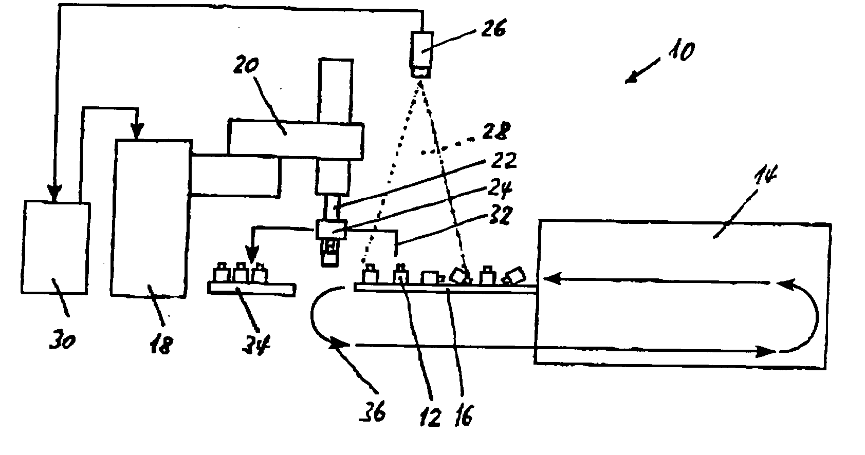
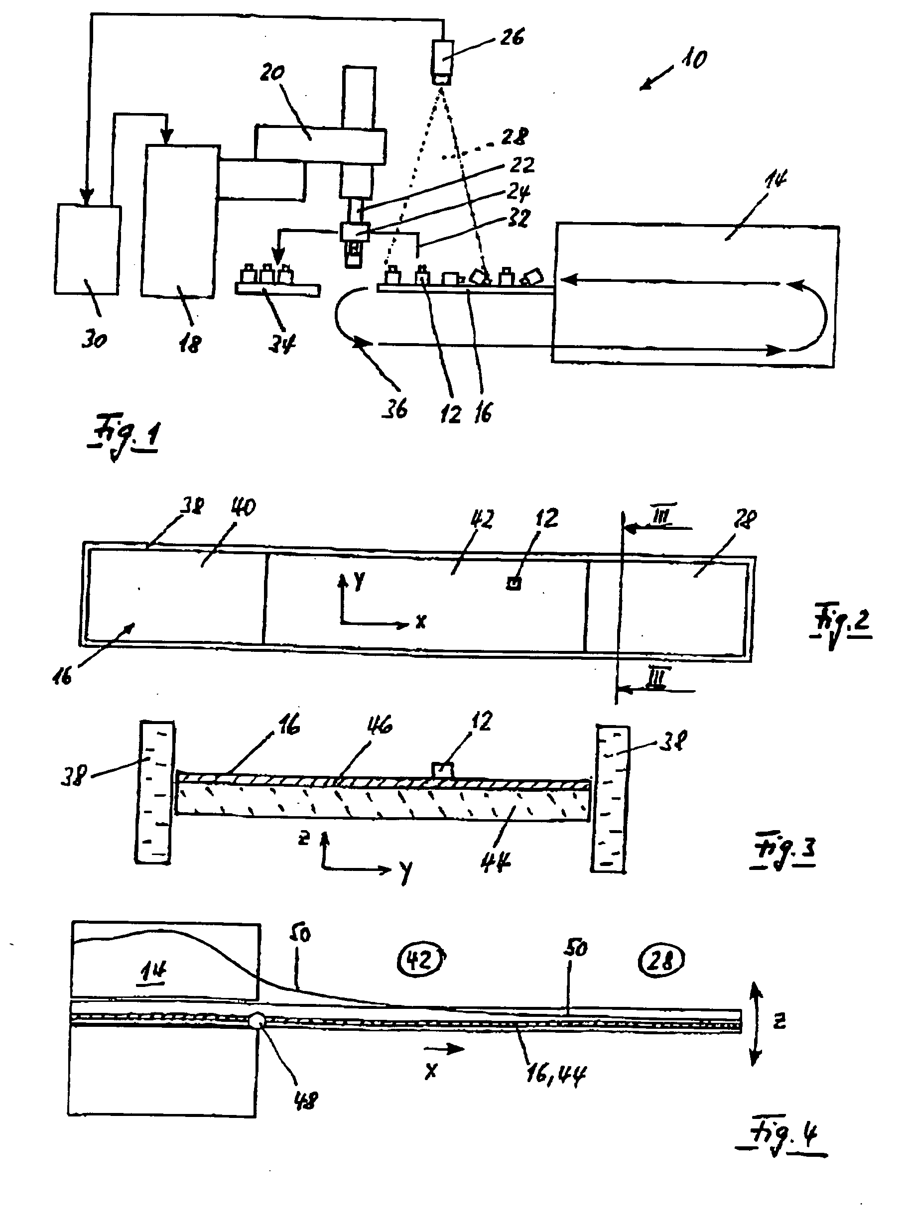
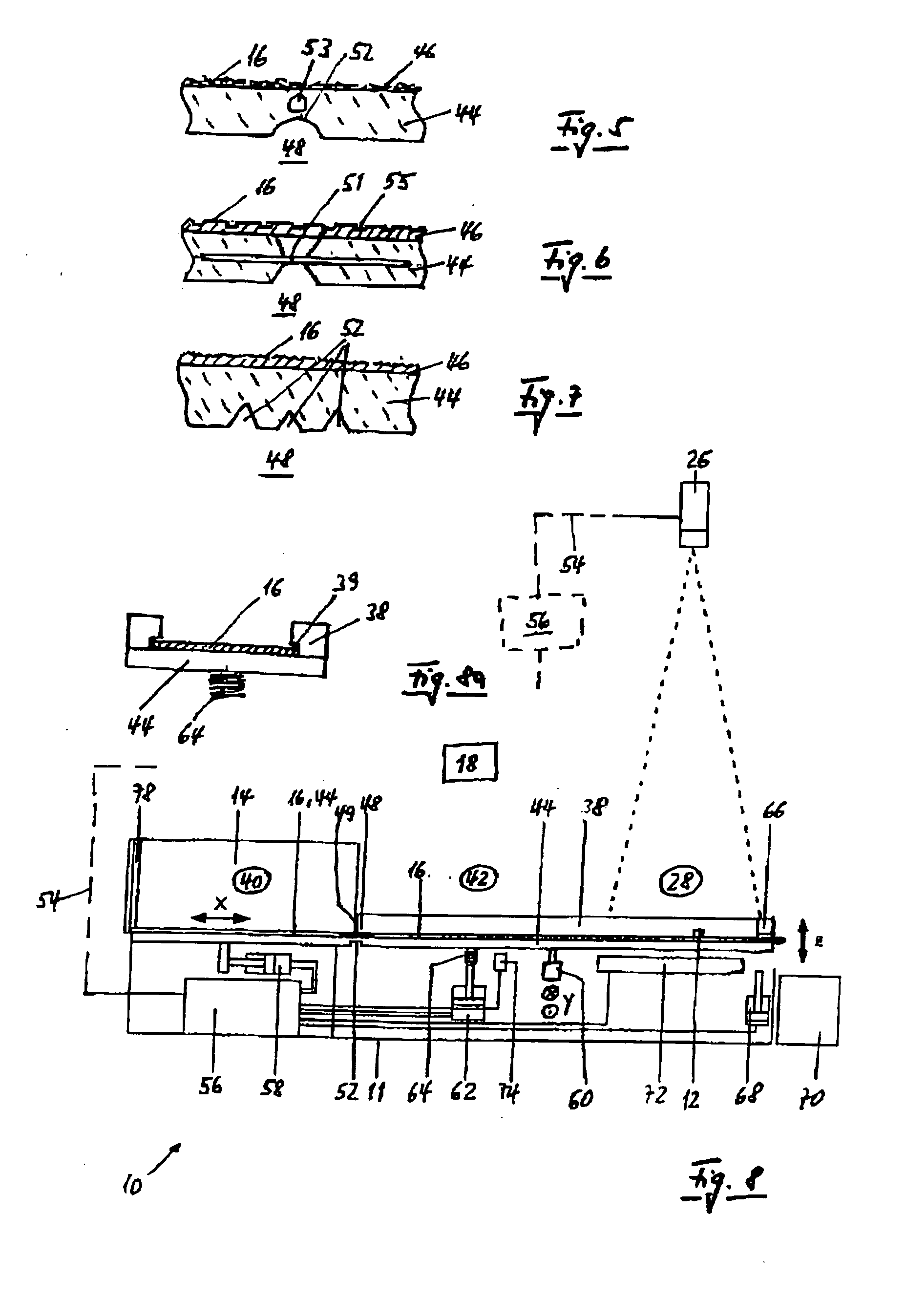
[0055]FIG. 2 shows a plan view of a conveyor surface 16 with an edge 38. The one-part conveyor surface 16 is functionally divided into a storage zone 40, a distribution zone 42 and a selection zone 28, the transition from zone to zone not being sharp, as shown by lines, but flowing within a region and without interruption on the surface, in particular between the distribution zone 42 and selection zone 28. The conveying direction of the bulk material items 12 is designated by the space coordinate x. In particular in the case of a broad oscillating conveyor surface 16, the forward feed of the bulk material items 12 may not only take place in the x-direction, but also in the x- and y-direction.

[0056]FIG. 3 shows the arrangement of a freely projecting oscillating conveyor arm 44 in the rest position, which bears an easily replaceable layer 46 which forms the oscillating conveyor surface 16 and can be displaced relative to the oscillating arm 44, at least in the x-direction, in the pre...


PUM


Abstract

A device (10) for feeding bulk material items (12) from a large mass into a randomly re-alignable, individually portioned disentangled position within the reach of a robot (18). A vision system comprising a camera (26) or a sensor records the number, position and alignment of the separated bulk material items (12). A processor (56) processes the sensor signals and generates control commands in actuators. The entire surface area of a one-piece oscillating conveyer surface (16) is supported by an oscillating conveyor arm (44). The surface lies on top of the arm and is horizontally displaceable in the x- or the x- and y-direction, extending together with the oscillating conveyor arm (44) and projecting in a freely supported manner from a storage zone (40) across a distribution zone (42) up to one front end of a selection zone (28) for the bulk material items (12). An oscillating motion (S) is generated in the z-direction with a continuously increasing amplitude (A) in the x-direction. The oscillating motion (S) alternates or is at least partially synchronous and co-ordinated with a forward feed or reverse transport of the bulk material items (12) in the x- or x- and y-direction.

Description

BACKGROUND OF THE INVENTION [0001] The invention relates to a device and a method for feeding bulk material items from a mass multiply arranged one above the other in a store into a randomly re-alignable, individually distributed and disentangled position within the reach of a robot, the device comprising a substantially horizontally arranged oscillating conveyor surface with means for the forward feed or reverse transport of the bulk material items in the x-direction or in the x- and y-direction of the space coordinates, means for exciting an at least partial oscillation of the oscillating conveyor surface in the z-direction of the space coordinates, a vision system with a camera or a sensor for individual detection of the number, position and alignment of the individual bulk material items, and a processor for processing the sensor signals and generating control commands to actuators. [0002] In the industrial production and fitting of consumer goods, more or less complicated mass-...

Claims


Application Information

Patent Timeline
Patent Type & Authority Applications(United States)
IPC IPC(8): B65G27/32B65G43/08B65G47/14
CPCB65G27/32B65G47/1492B65G43/08
Inventor BUCHI, FELIX
Owner BUCHI FELIX
Why Eureka
Eureka Blog
Learn More