
Sensor according to the runtime principle with a detector unit for mechanical-elastic waves

a sensor and runtime principle technology, applied in the direction of converting sensor output using wave/particle radiation, instruments, printing, etc., can solve the problems of negative operating point change, all form deviations from normal shape, and overall length of position sensor

Active Publication Date: 2005-09-15
ASM AUTOMATION SENSORIK MESSTECHN GMBH
View PDF9 Cites 10 Cited by
  • Summary
  • Abstract
  • Description
  • Claims
  • Application Information

AI Technical Summary

Problems solved by technology

This is in unfavorable in several respects, for instance with employment of the position sensor in places, which are subjected to mechanical, in particular dynamic mechanical loads or also thermal loads, which change the magnetic parameters of the bias magnet and accelerate in particular its aging process, which entail likewise a change of the magnetic parameters.
Additionally all form deviations from the normal shape, arising with the manufacturing of the bias magnet, are unfavorable in the same way.
A further disadvantage consisted in the fact that in case of a too close approach of the position magnet to the detector coil, the operating point is changed negatively.
This however always resulted in an overall length of the position sensor, which was clearly larger than its measuring range.

Method used


Image

  • Sensor according to the runtime principle with a detector unit for mechanical-elastic waves
  • Sensor according to the runtime principle with a detector unit for mechanical-elastic waves
  • Sensor according to the runtime principle with a detector unit for mechanical-elastic waves

Examples


Embodiment Construction

[0042] An embodiment in accordance with the invention is described in greater by way of example detail hereinafter, with reference to the Figures. The drawings show:

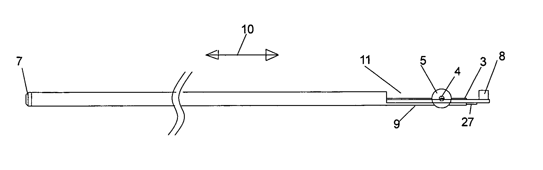
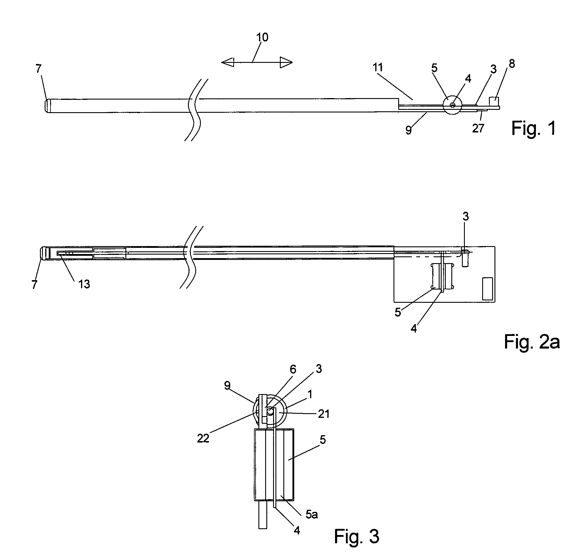
[0043]FIG. 1: a plan view on the position sensor,

[0044]FIG. 2: a side view with partially sectioned coil in accordance with FIG. 1,

[0045]FIG. 3: a front view in accordance with FIG. 1,

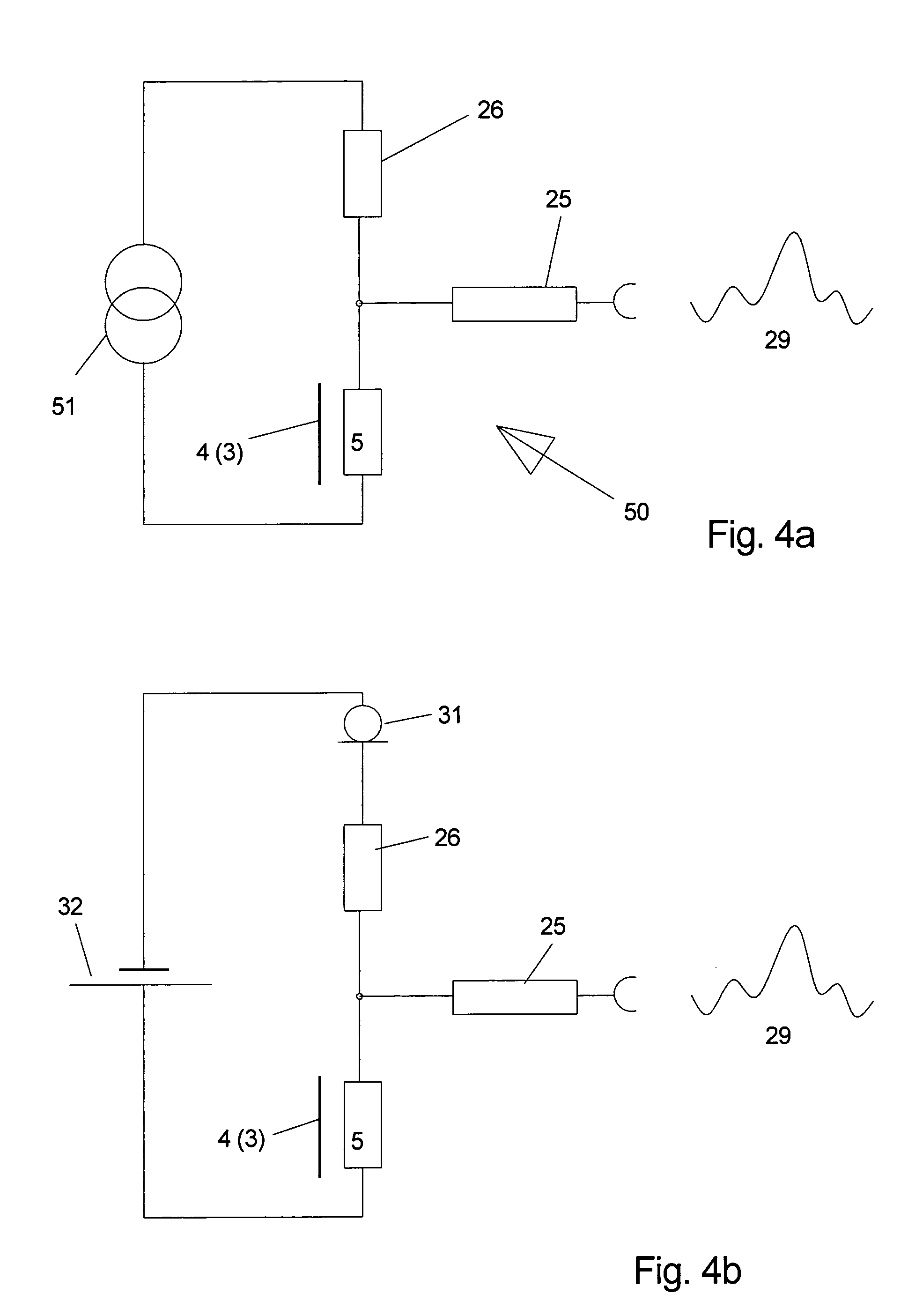
[0046]FIG. 4a, b: the detector coil in a series circuit,

[0047]FIG. 4c: the detector coil in a measuring bridge,

[0048]FIG. 4d: a difference amplifier for the subsequent processing of the position signal,

[0049]FIG. 5: sectional views through various detector arrangements,

[0050]FIG. 6: sectional views through a detector arrangement on the wave body,

[0051]FIG. 7: sectional views similar to line VII-VII in accordance with FIG. 3,

[0052]FIG. 8: detector arrangement with toroidal coil,

[0053]FIG. 9: further detector arrangements, and

[0054]FIG. 10a, 10b: additional detector arrangements.

[0055] The FIGS. 1 and 2 show a sensor element, in w...


PUM


Abstract

A detector unit apparatus and method for operating and producing a detector unit to be adapted to varying environmental influences or to its own, in particular mechanical, electrical or magnetic parameters of the detector unit, which are dependent on measuring lengths. An inventive positional sensor operating according to the running time principle of a mechanically elastic shaft and comprising a waveguide, a positional element, e.g. a positional magnet, which can be displaced in particular along the waveguide, in addition to a detector assembly that is located on the waveguide and comprises a detector coil wherein the detector assembly has a current source so that a current can flow through the detector coil.

Description

I. AREA OF APPLICATION [0001] The invention concerns position sensors, in particular their detector unit, based on the principle of the runtime measurement of mechanical-elastic impulses in a waveguide, which include, beside this waveguide, a position element that can move relatively to it and that is generating or detecting the mechanical-elastic wave. II. TECHNICAL BACKGROUND [0002] The waveguide usually consists of a pipe, a wire or a strip, and can serve also as an electrical conductor. The waveguide can be arranged further in a form-giving, linear or circular body made of non-magnetic material, e.g. plastic or metal, for the support and bearing of the waveguide. [0003] Based on the Wiedemann effect, a current pulse fed into the waveguide produces, by its overlaying with a laterally on the magnetostrictive waveguide oriented external magnetic field, which is originating from a position element, in particular from a position magnet, generates a torsion impulse of a mechanical ela...

Claims


Application Information

Patent Timeline
IPC IPC(8): G01D5/48
CPCG01D5/485
Inventor STEINICH, KLAUS MANFREDJIGOU, LIU
Owner ASM AUTOMATION SENSORIK MESSTECHN GMBH
Learn More