Apparatus and method for synchronizing visual/audible alarm units in an alarm system

a technology of visual/audible alarm and alarm system, which is applied in the field of circuits of electronic alarm systems, can solve problems such as the loss of intensity of strobes, and achieve the effect of low input voltag

Inactive Publication Date: 2005-09-15
WHEELOCK & CO
View PDF10 Cites 15 Cited by
  • Summary
  • Abstract
  • Description
  • Claims
  • Application Information

AI Technical Summary

Benefits of technology

[0014] The alarm unit is capable of detecting a low input voltage. When the detected voltage drops below a predetermined threshold, the alarm unit will lower the frequency of the visual alarm signal, preferably a strobe, to ensure that the strobe flashtube receives enough energy to flash at an adequate brightness.

Problems solved by technology

However, when the voltage source is at 80% of nominal value, the strobe may lose some intensity which could prove crucial during a fire emergency.

Method used


Image

  • Apparatus and method for synchronizing visual/audible alarm units in an alarm system
  • Apparatus and method for synchronizing visual/audible alarm units in an alarm system
  • Apparatus and method for synchronizing visual/audible alarm units in an alarm system

Examples


Embodiment Construction

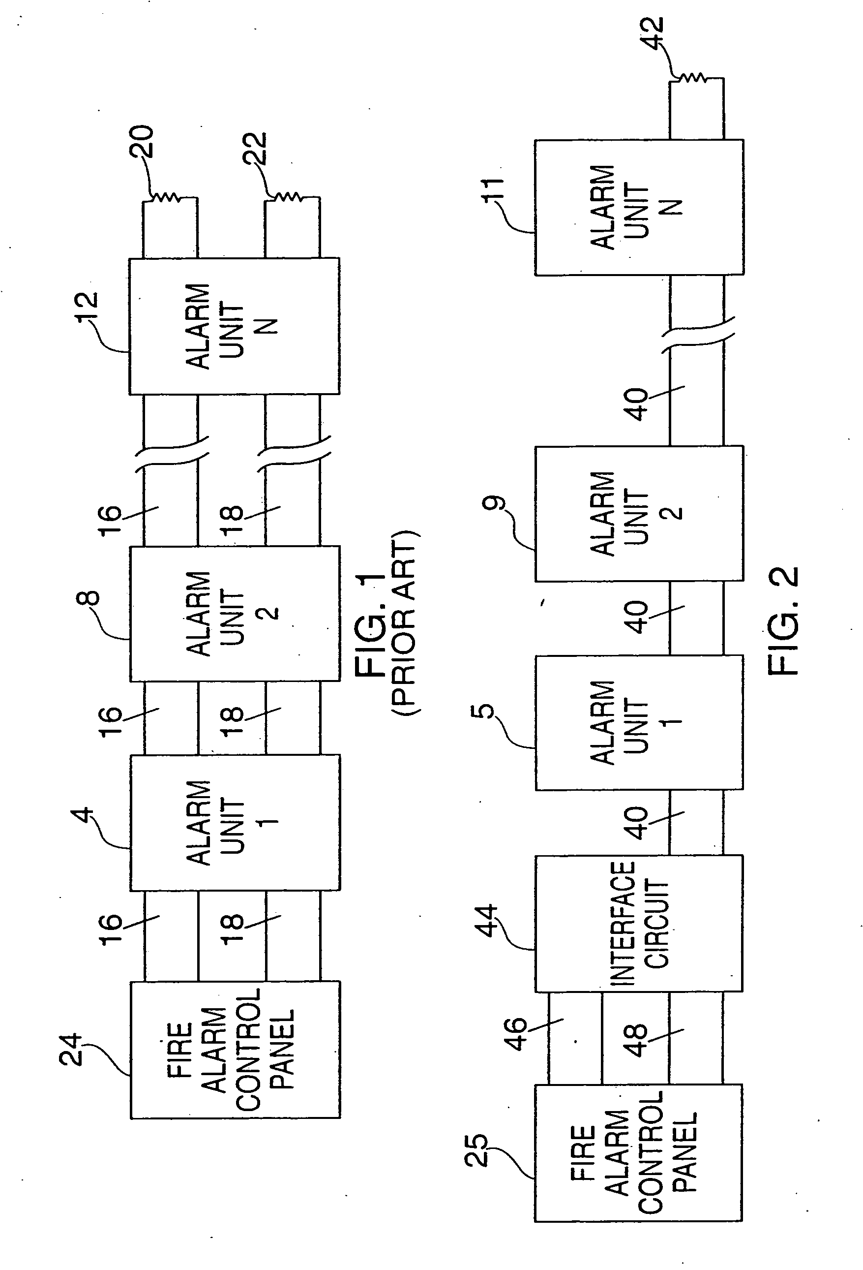
[0037] In the conventional prior art alarm system shown in FIG. 1, which provides for both visual and audio alarm signals, multiple alarm units 4, 8 and 12, numbered 1 through N, are connected by two common loops 16, 18 having the usual end of the line resistors 20, 22, respectively. The alarm units have both audio and visual signaling capabilities. The first control loop 16 handles visual control signals being output from the fire alarm control panel 24 to the alarm units, and the second control loop 18 handles audio control signals being output from the fire alarm control panel 24 to the alarm units.

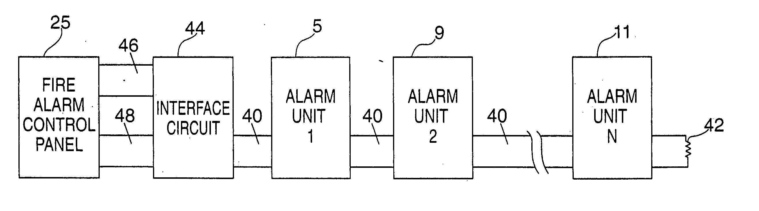
[0038]FIG. 2 is a block diagram of an embodiment of the alarm system of the present invention. By contrast to FIG. 1, multiple alarm circuits 5, 9 and 11, numbered 1 to N, are connected in a single control loop 40 with the usual end of the line resistor 42. In accordance with the invention, all units are caused to flash and sound synchronously using an interface control circuit 44 and...


PUM


Abstract

An apparatus and concomitant method of reducing the number of synchronization pulses transmitted to the alarm units for increasing the reliability of the overall alarm system is disclosed. The synchronization signal is implemented as a reference or reset signal from which the alarm units derive a reference time to begin activation of the alarm units. Thus, when an alarm unit receives a reference synchronization pulse, the alarm unit applies the reference synchronization pulse as a reference point in time to trigger a series of flashes or audio tones. A second signal sent in close proximity to the synchronization signal is implemented to trigger a second function of the alarm units, such as a silence function.

Description

[0001] This is a continuation of application Ser. No. 10 / 602,926, filed Jun. 24, 2003, which is in turn a continuation of application Ser. No. 10 / 119,229, filed Apr. 9, 2002 (U.S. Pat. No. 6,583,718), which is a continuation of application Ser. No. 09 / 793,215, filed on Feb. 26, 2001 (U.S. Pat. No. 6,369,696), which is a continuation of application Ser. No. 09 / 153,105, filed on Sep. 15, 1998 (U.S. Pat. No. 6,194,994), which is a continuation-in-part of application Ser. No. 09 / 074,328, filed on May 7, 1998 (U.S. Pat. No. 5,982,275), which is a continuation of application Ser. No. 08 / 807,063, filed on Feb. 27, 1997 (U.S. Pat. No. 5,751,210), which is a divisional application of application Ser. No. 08 / 407,282, filed on Mar. 20, 1995 (U.S. Pat. No. 5,608,375), where each of the above applications is herein incorporated by reference in their entireties. [0002] The invention relates generally to an alarm system for providing visual and / or audio warnings and, more particularly, to an appar...

Claims


Application Information

Patent Timeline
Patent Type & Authority Applications(United States)
IPC IPC(8): G08B7/06G08B27/00
CPCG08B3/10G08B5/38G08B7/06G08B27/00G08B25/04G08B25/14G08B17/00
Inventor CURRAN, JOHN W.KOSICH, JOSEPH
Owner WHEELOCK & CO
Why Eureka
Try Eureka