Optimal Tapered Band Positioning to Mitigate Flare-End Ringing of Broadband Antennas

a broadband antenna and tapered band technology, applied in the direction of antennas, electrical equipment, antenna feed intermediates, etc., can solve the problems of reducing the radiation efficiency of lower signal frequency components, and achieve the effects of reducing radiation efficiency, reducing interference, and improving the impedance characteristics and filter response of antennas

Inactive Publication Date: 2005-09-15
REALTRONICS CORP
View PDF20 Cites 29 Cited by
  • Summary
  • Abstract
  • Description
  • Claims
  • Application Information

AI Technical Summary

Benefits of technology

[0023] This invention improves prior art by combining impedance matching with wave propagation techniques to achieve marginal flare-end ringing. This is achieved by changing the distribution of impedance tapering throughout the antenna and although it is depicted on a bow-tie antenna only to illustrate the concept, the technique is effective on any shape of impedance tapered antennae. In particular, the first impedance band is optimally placed at a position on each antenna leaf that minimizes interference between the front edge of the transmitted impulse and the reflected pulse that is generated by the discrete interface. This balancing strategy reduces the radiation efficiency for lower signal frequency components, which improves the impedance characteristics and filter response of the antenna. This invention further eliminates rising edge pulse distortion by moving the reflection from the first band away from the front edge of the impulse. The approach provides an optimal balance between radiation efficiency, end-fire ringing, and signal distortion.

Problems solved by technology

This balancing strategy reduces the radiation efficiency for lower signal frequency components, which improves the impedance characteristics and filter response of the antenna.

Method used


Image

  • Optimal Tapered Band Positioning to Mitigate Flare-End Ringing of Broadband Antennas
  • Optimal Tapered Band Positioning to Mitigate Flare-End Ringing of Broadband Antennas
  • Optimal Tapered Band Positioning to Mitigate Flare-End Ringing of Broadband Antennas

Examples


Embodiment Construction

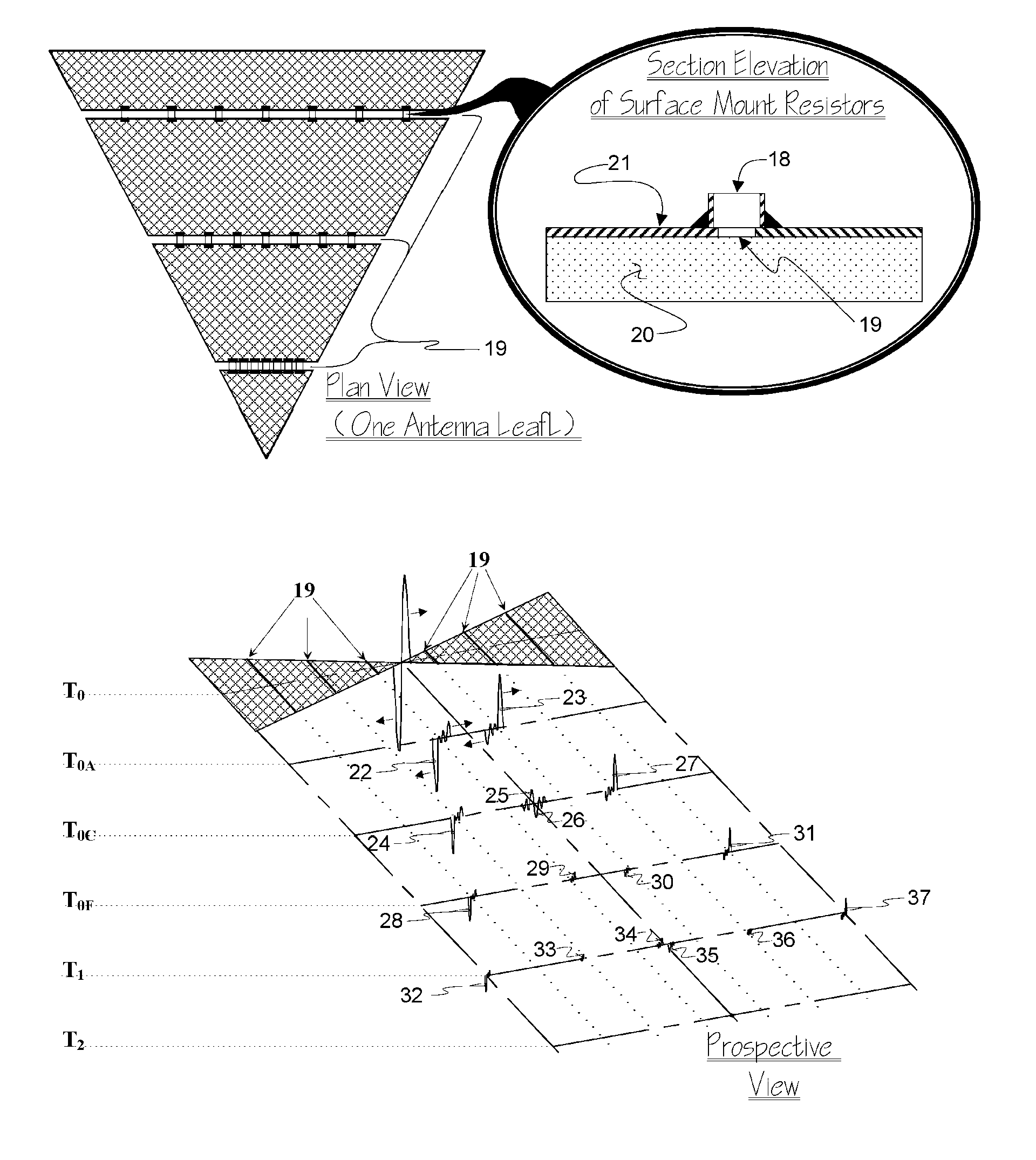
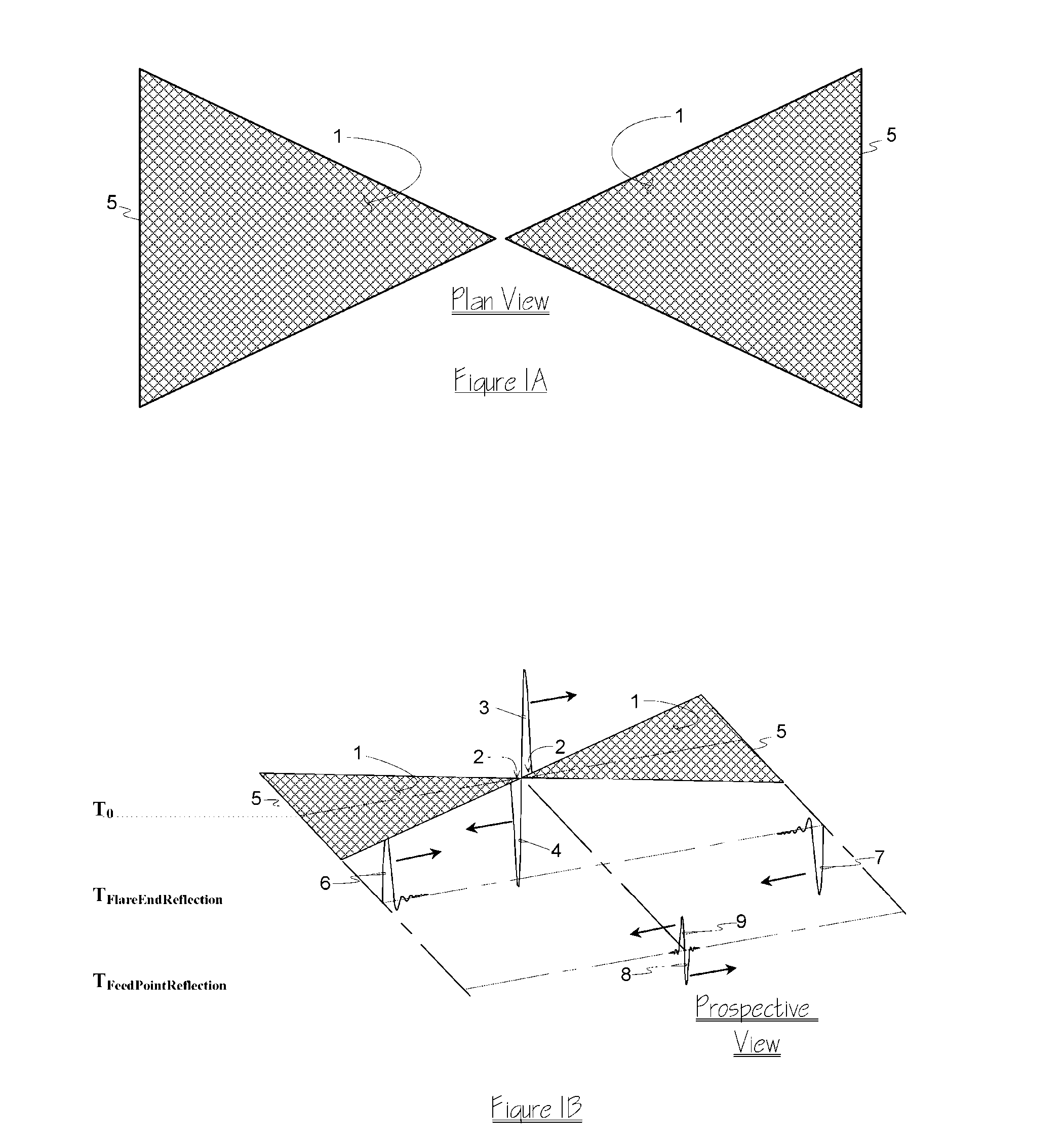
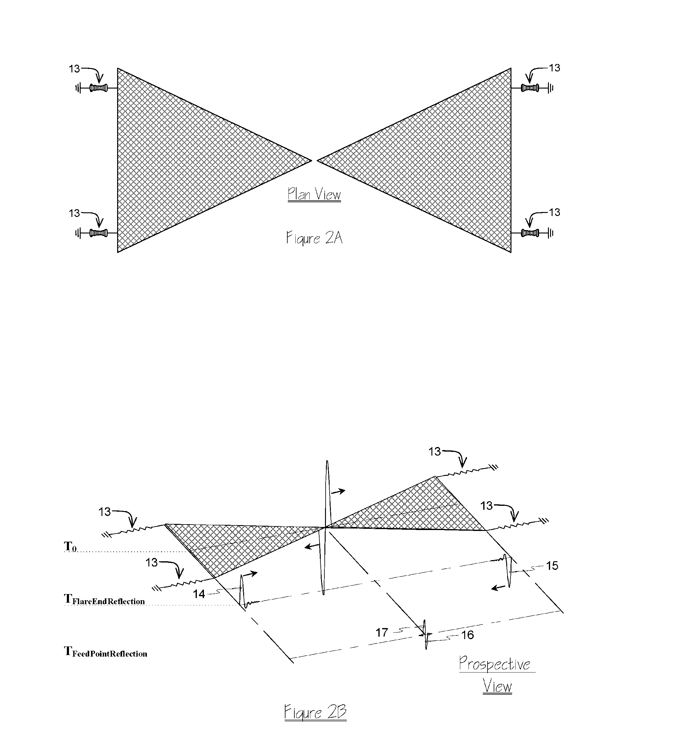
[0033] This invention is related to the improvement of antennas that are capable of transmitting an impulse signal by providing a method that balances radiation efficiency, end-fire ringing, and impulse distortion to improve the wide band impedance characteristics and wave reflections on the surface of an antenna. This novel approach was first published in [11] with an improvement to [10] that included removal of the first two impedance tapered bands. The position of each tapered impedance interface in [11], including the position of the first two bands that were removed from the antenna, was based on traditional and widely published mathematical calculations on the subject [9]. This invention discloses a novel improvement to [10] and [11] that optimally positions the first interface, most often in the half of the antenna that is closest to the flare-end, to eliminate the occurrence of interference from the interface induced pulse reflection before the front edge of the feed point i...


PUM


Abstract

A novel approach is disclosed that mitigates flare-end ringing induced distortion of impulse signals that are transmitted from an electromagnetic radiator. Conventional tapering suppresses energy in the return path by impedance loading the antenna element at the expense of reduced radiation efficiency. This disclosure presents a method that balances the trade-off between radiation efficiency and return path energy suppression while it simultaneously minimizes taper induced signal distortion effects on the front edge of the transmitted impulse. The balance between radiation efficiency, end-fire ringing, and impulse distortion is achieved by placing impedance loading at only at or near the second half of the antenna element. Recent disclosures show the advantage of determining the position of each band through mathematical calculation and by subsequently removing select bands near the feed point to move the reflected pulse away from the front-edge of the transmitted impulse. This disclosure will show that optimal placement of the first tapered band is substantially more critical. The reflection caused by this interface must reach the original impulse at a position that will minimally interfere with its front edge.

Description

CROSS-REFERENCE TO RELATED APPLICATIONS [0001] Current US Class: 343 / 793, 343 / 807, 343 / 845 [0002] International Class: H01Q 001 / 38, 48 [0003] Field of Search: 250 / 216, 342 / 379, 343 / 727, 730, 739, 740, 775, 777, 793, 795, 807, 813, 814, 815, 819, 820, 826, 828, 841, 845, 912, 913 OTHER PUBLICATIONS [0004] [1] R. L. Carrel, “The characteristic impedance of two infinite cones of arbitrary cross section,” IEEE Trans. Antennas Propagation, vol. AP-6, no. 2, pp. 197-201, 1958. [0005] [2] T. T. Wu and R. W. P. King, “The cylindrical antenna with nonreflecting resistive loading,” IEEE Trans. Antennas Propagation, vol. 13, no. 3, pp. 369-373, 1965. [0006] [3] Wu et al., “The Cylindrical Antenna with Nonreflecting Resistive Loading”, IEEE Transactions on Antennas and Propagation, vol. AP-13, No. 3, pp. 369-373, May 1965. [0007] [4] Shen, “An Experimental Study of the Antenna with Nonreflecting Resistive Loading”, IEEE Transactions on Antennas and Propagation, vol. AP15, No. 5, Sep. 1967, pp. ...

Claims


Application Information

Patent Timeline
Patent Type & Authority Applications(United States)
IPC IPC(8): H01Q9/28H01Q13/00
CPCH04B2001/6908H01Q9/28
Inventor THOMPSON, SCOTT RANDALLASKILDSEN, BERNT ASKILD
Owner REALTRONICS CORP
Why Eureka
Try Eureka