LCD comprising backlight and reflective polarizer on front panel

Inactive Publication Date: 2005-09-15
NITTO DENKO CORP
View PDF10 Cites 31 Cited by
  • Summary
  • Abstract
  • Description
  • Claims
  • Application Information

AI Technical Summary

Benefits of technology

[0015] The objectives of the disclosed invention are to decrease optical losses in LCD disp

Problems solved by technology

However, single crystals are expensive materials and cannot be readily formed into the desired shapes or configurations, which are required for particular applications.
However, these

Method used


Image

  • LCD comprising backlight and reflective polarizer on front panel
  • LCD comprising backlight and reflective polarizer on front panel
  • LCD comprising backlight and reflective polarizer on front panel

Examples


Example

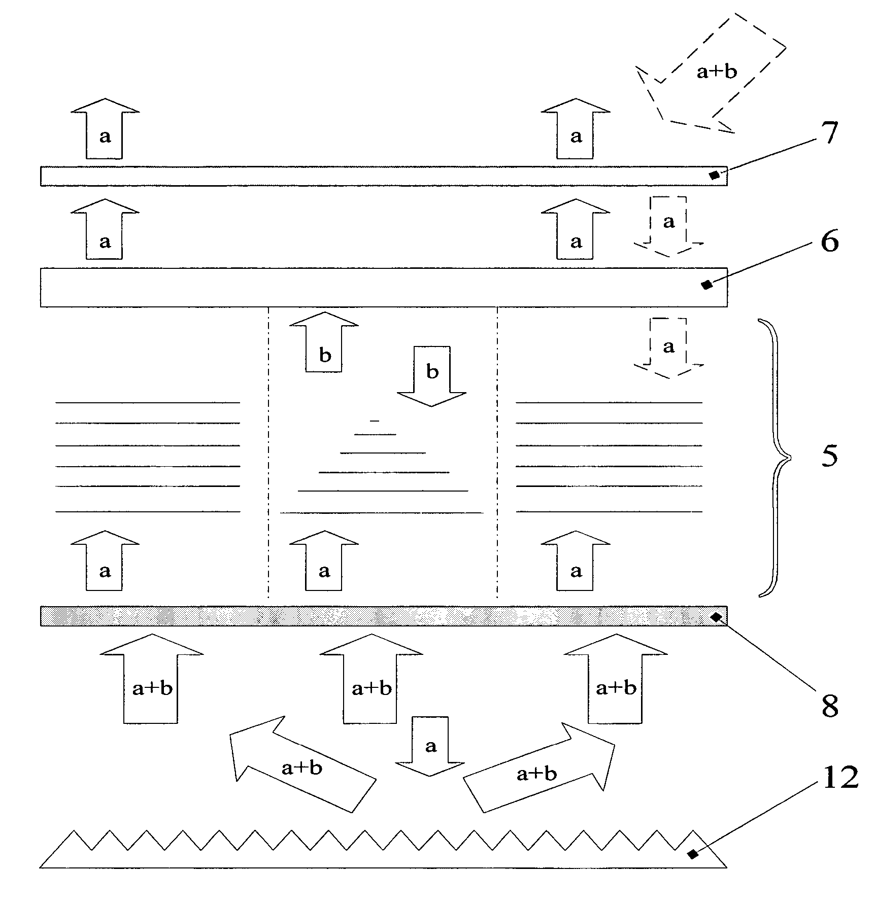
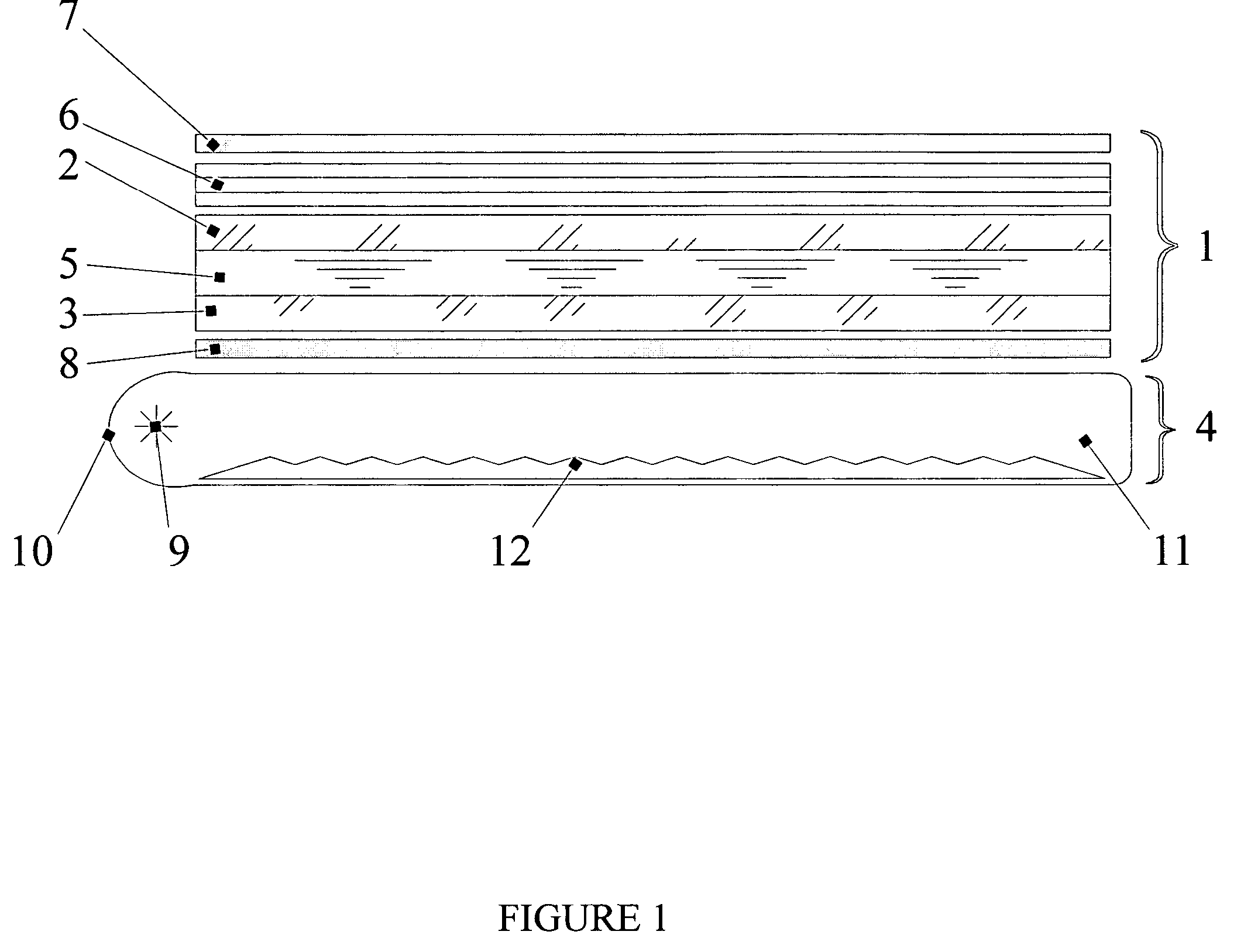
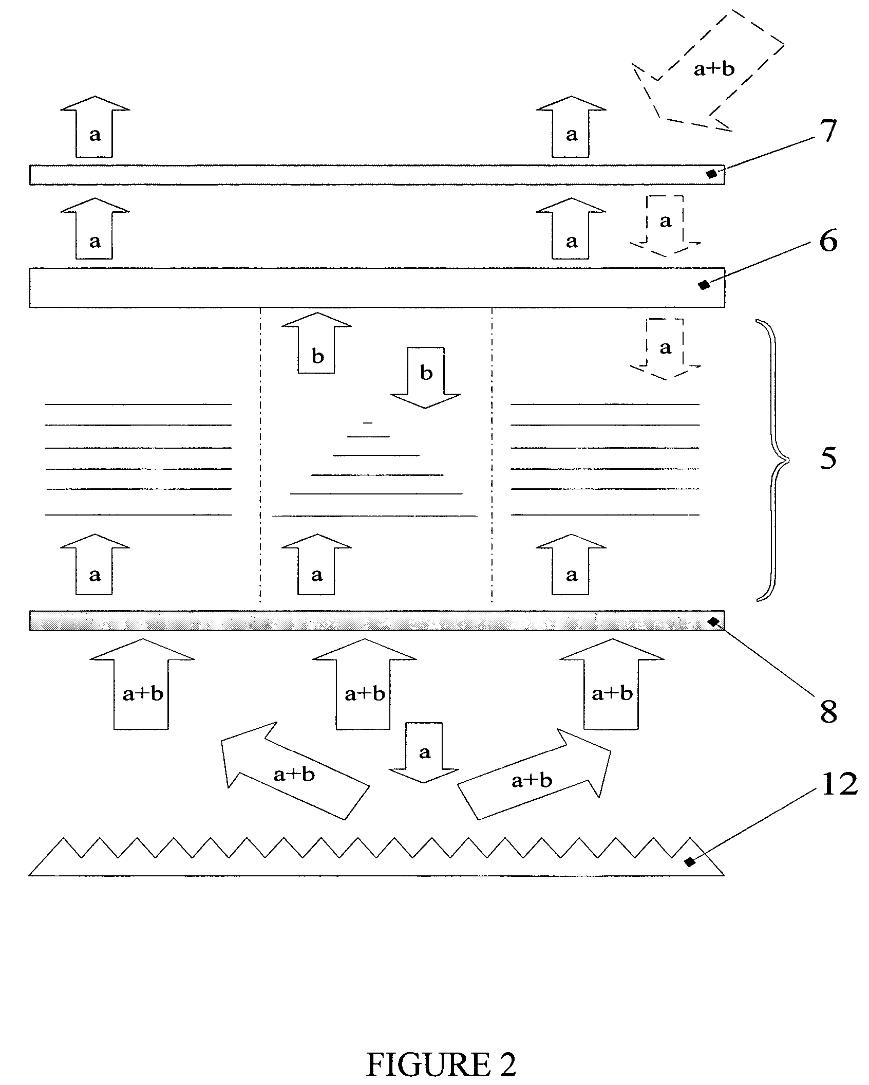
[0025]FIG. 1 shows a cross section of the LCD that comprises a liquid crystal cell 1, formed by front panel 2 and rear panel 3 with polarizing means on each of them, and a backlight system 4. A layer of liquid crystal 5 is placed between said panels. The polarizing means of the front panel include a reflective polarizer 6 and a dichroic polarizer 7 applied on top of the reflective polarizer. The transmission axes of both said polarizers coincide. The rear panel comprises a linear polarizer 8 of any type.

[0026] The backlight system is an optical cavity of the edge backlight type, which includes a lamp 9 in a reflective lamp housing 10. The light emitted by the lamp is fed to a light guide 11 where it propagates until encountering a diffuse reflective structure, or layer 12 such as a spot array. This discontinuous array of spots is arranged to reflect the light and direct it toward the liquid crystal cell. Ambient light entering the optical cavity may also strike a spot or escape fro...


PUM


Abstract

A liquid crystal display with a backlight is described. The liquid crystal cell comprising a front panel and a rear panel with polarizing means on each panel, and the front polarizing means includes a reflective polarizer and a dichroic polarizer.

Description

RELATED APPLICATIONS [0001] This application claims priority of Provisional Application Ser. No. 60 / 551,935, filed Mar. 9, 2004.FIELD OF THE INVENTION [0002] The present invention relates to the field of data display devices. More specifically, this invention relates to liquid crystal displays with backlight systems possessing improved optical characteristics and decreased optical losses. BACKGROUND OF THE INVENTION [0003] Flat panel displays or liquid crystal displays (LCDs) are popular display devices for conveying information generated by computers. Reduced weight and size of a flat panel display offer great advantages over cathode ray tube (CRT) displays. High-quality flat panel displays are typically backlighted, that is, a source of illumination is placed behind the LCD layers to facilitate visualization of the image. Flat panel LCD devices are used in many applications including the computer industry, where flat panel LCD units are an excellent display choice for laptop compu...

Claims


Application Information

Patent Timeline
IPC IPC(8): G02F1/1335
CPCG02F1/133536G02F2001/133545G09G2360/145G09G3/3406G09G2320/0646G02F2001/133562G02F1/133545G02F1/133562G02F1/1335
Inventor LAZAREV, PAVEL I.PAUKSHTO, MICHAEL V.
Owner NITTO DENKO CORP
Why Eureka
Try Eureka