Multisignature method, apparatus, program, and system

a multi-signature and key technology, applied in the field of multi-signature methods, apparatuses, programs, systems, can solve the problems of inhibiting and achieve the effect of preventing the increase of the key siz

Inactive Publication Date: 2005-09-15
KK TOSHIBA
View PDF1 Cites 50 Cited by
  • Summary
  • Abstract
  • Description
  • Claims
  • Application Information

AI Technical Summary

Benefits of technology

[0038] An object of the present invention is to provide a multisignature method, apparatus, program, and system which are capable of preventing an increase of a size of a key even when signature order advances in a case where a ground for security is laid in operation difficulty of inverse function operation of a trapdoor one-way function, represented by an RSA problem.

Problems solved by technology

Therefore, in a case where the ground for the security is laid in the difficulty in the inverse function operation of the one-way function represented by the RSA problem, even when the signature order advances, the increase of the size of the key can be inhibited.

Method used


Image

  • Multisignature method, apparatus, program, and system
  • Multisignature method, apparatus, program, and system
  • Multisignature method, apparatus, program, and system

Examples


first embodiment

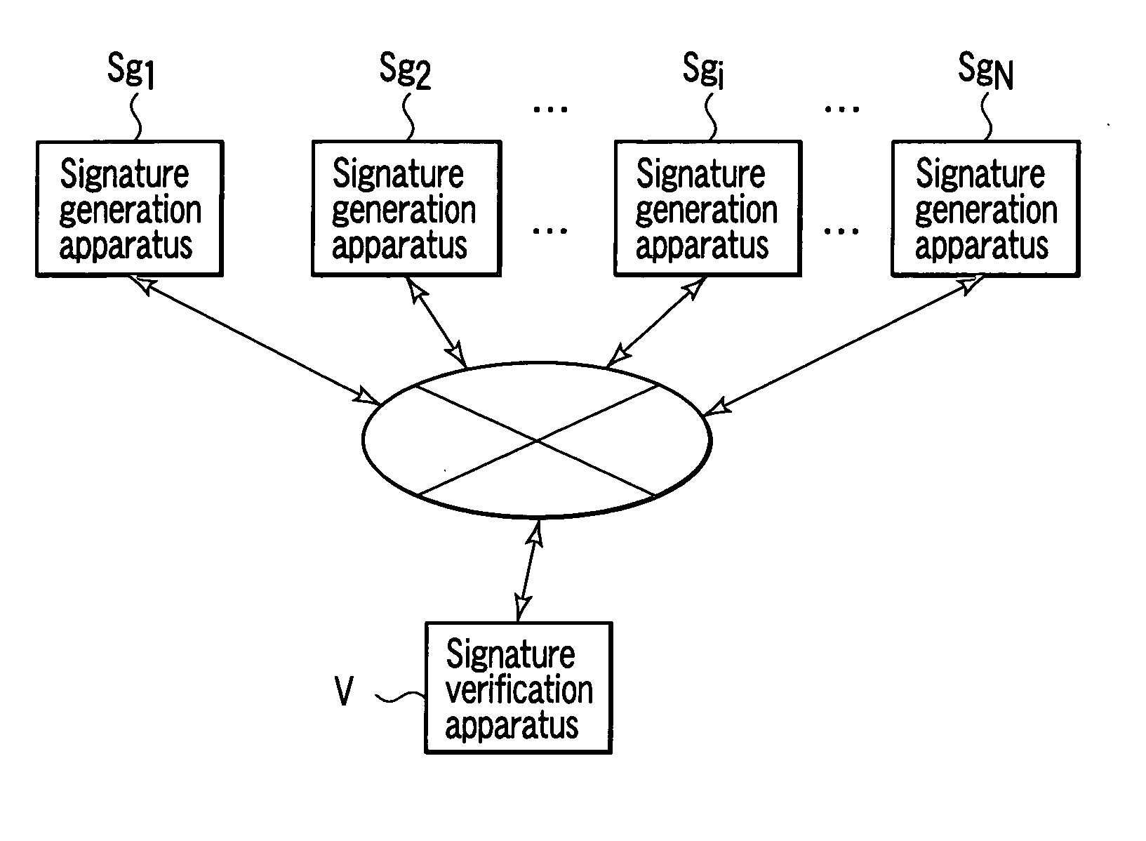
[0064]FIG. 8 is a schematic diagram showing a constitution of a multisignature system according to a first embodiment of the present invention. In this multisignature system, N signature generation apparatuses Sg1 to SgN and one signature verification apparatus V are connected to one another via a network.

[0065] Here, the respective signature generation apparatuses Sg1 to SgN have the same hardware constitution. Here, the signature generation apparatus Sgi will be described as a representative example.

[0066] As shown in FIG. 9, the signature generation apparatus Sgi comprises a memory 1, an input / output section 2, a random number generator 3, a random number memory 4, an arithmetic device 5, an Hi′ function operation section 6, a Gi function operation section 7, a public key cryptosystem signature generation section 8s, a secret key memory 9, and a control section 10s. The respective elements 1 to 10 excluding the random number generator 3 and the secret key memory 9 are connected...

second embodiment

[0148] Next, a multisignature system according to a second embodiment of the present invention will be described with reference to FIGS. 8 to 10.

[0149] That is, in the present embodiment, a hardware constitution is similar to that of the first embodiment, but, unlike the first embodiment, a system shown in FIG. 7 is executed instead of the system shown in FIG. 6. Accordingly, a control section 10s of a signature generation apparatus Sgi controls sections 1 to 9 as shown in FIG. 15, and a control section 10v of a signature verification apparatus v controls the respective sections 1 to 8v as shown in FIG. 16.

[0150] Next, an operation of a multisignature system constituted as described above will be described with reference to flowcharts of FIGS. 15 and 16.

[0151] (Signature Generation Process)

[0152] A signer utilizes the signature generation apparatus Sgi in order to attach self signature to document data x constituted by concatenating self identifier IDi to document data x′ with r...


PUM


Abstract

According to embodiments of the present invention, in a case where a ground for security is laid in difficulty in executing an inverse function operation of a trapdoor one-way function, represented by an RSA problem, even when a signature order advances, an increase of a size of a key can be inhibited. For example, when the first partial data σi-1,L exceeding (k0+k1) bits when concatenating a random number ri of k0 bits is excluded from an input of binary operation on an input side of a signature generation function. Accordingly, a size of an operation result si of the binary operation is set to be constant at (k0+k2) bits, and, as a result, an input size (key length k bits) of an RSA signature generation function is set to be constant.

Description

CROSS-REFERENCE TO RELATED APPLICATIONS [0001] This application is based upon and claims the benefit of priority from prior Japanese Patent Application No. 2004-016109, filed Jan. 23, 2004, the entire contents of which are incorporated herein by reference. BACKGROUND OF THE INVENTION [0002] 1. Field of the Invention [0003] The present invention relates to a multisignature method in which a plurality of signers successively perform a signature generating process with respect to a certain document to thereby generate one signature, apparatus, program, and system. [0004] 2. Description of the Related Art [0005] In general, a cryptosystem can be classified into two types: a common key cryptosystem; and a public key cryptosystem. The public key cryptosystem has an advantage that a necessity for key distribution raising problem in a common key system is obviated. [0006] For example, in the public key cryptosystem, users A, B, . . . generate a set of a public key and a secret key, and regi...

Claims


Application Information

Patent Timeline
Patent Type & Authority Applications(United States)
IPC IPC(8): H04L9/32H04K1/00
CPCH04L9/3255H04L9/3249
Inventor KOMANO, YUICHIOHTA, KAZUOKAWAMURA, SHINICHISHIMBO, ATSUSHI
Owner KK TOSHIBA
Why Eureka
Try Eureka