Portable device
- Summary
- Abstract
- Description
- Claims
- Application Information
AI Technical Summary
Benefits of technology
Problems solved by technology
Method used
Image
Examples
embodiment 1
[0071] (Embodiment 1)
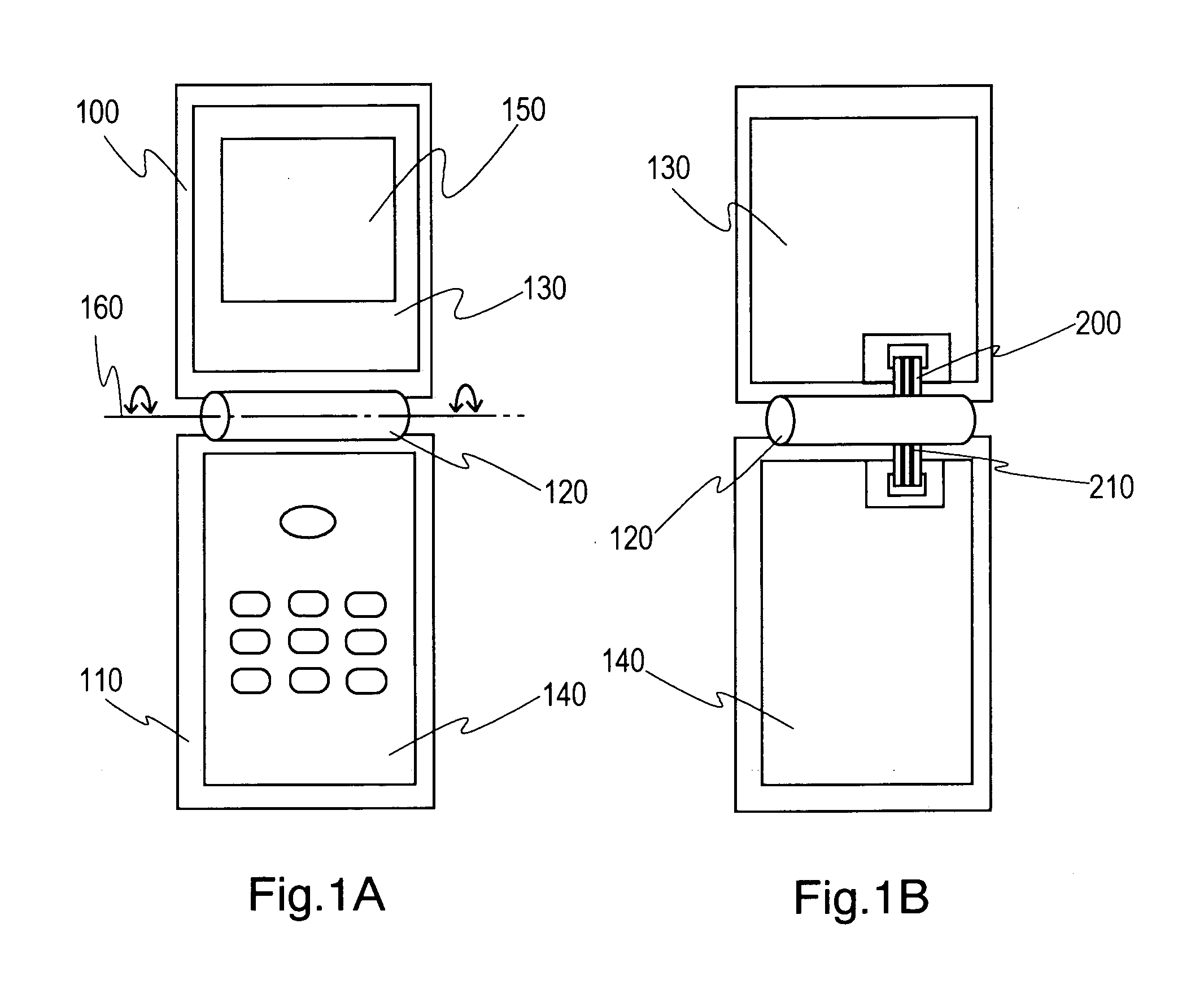
[0072]FIG. 1 is a schematic configuration diagram of a portable device according to Embodiment 1. FIG. 1A is a general view of the portable device, while FIG. 1B is a conceptual diagram showing the arrangement of an optical waveguide film in a connection section between a first housing and a second housing. It should be noted that an exterior is provided in practice for covering the connection section. However, in order to clearly show the arrangement of an optical waveguide film, the exterior is omitted in all the drawings including FIG. 1B.
[0073] The following description is given using a general portable phone as an example of a portable device. However, its basic structure is common also to portable devices such as a notebook personal computer and a PDA (Personal Digital Assistance) capable of being opened and closed freely.
[0074] In FIG. 1A, a first housing 100 and a second housing 110 are connected through a connection section 120 having a hinge capable ...
embodiment 2
[0112] (Embodiment 2)
[0113]FIG. 10 is a schematic configuration diagram of a portable device according to Embodiment 2. FIG. 10A is a general view of the portable device. FIG. 10B is a conceptual diagram showing the arrangement of an optical waveguide film 200 in the connection section 120 for optically connecting the first housing 100 with the second housing 110. This configuration is the same as Embodiment 1 except that at least the optical waveguides 210 in the optical waveguide film 200 is arranged oblique relative to the pivot axis 160 of the connection section 120.
[0114] Embodiment 2 achieves further thickness reduction in a portable device according to Embodiment 1. The reason for this is described below. Table 1 shows the relative optical loss generated by bending of the optical waveguide film 200 as a function of the helix angle Φ (see FIG. 11A) between the pivot axis 160 of the connection section 120 and the optical waveguide 210 and using the thickness of the optical wav...
embodiment 3
[0122] (Embodiment 3)
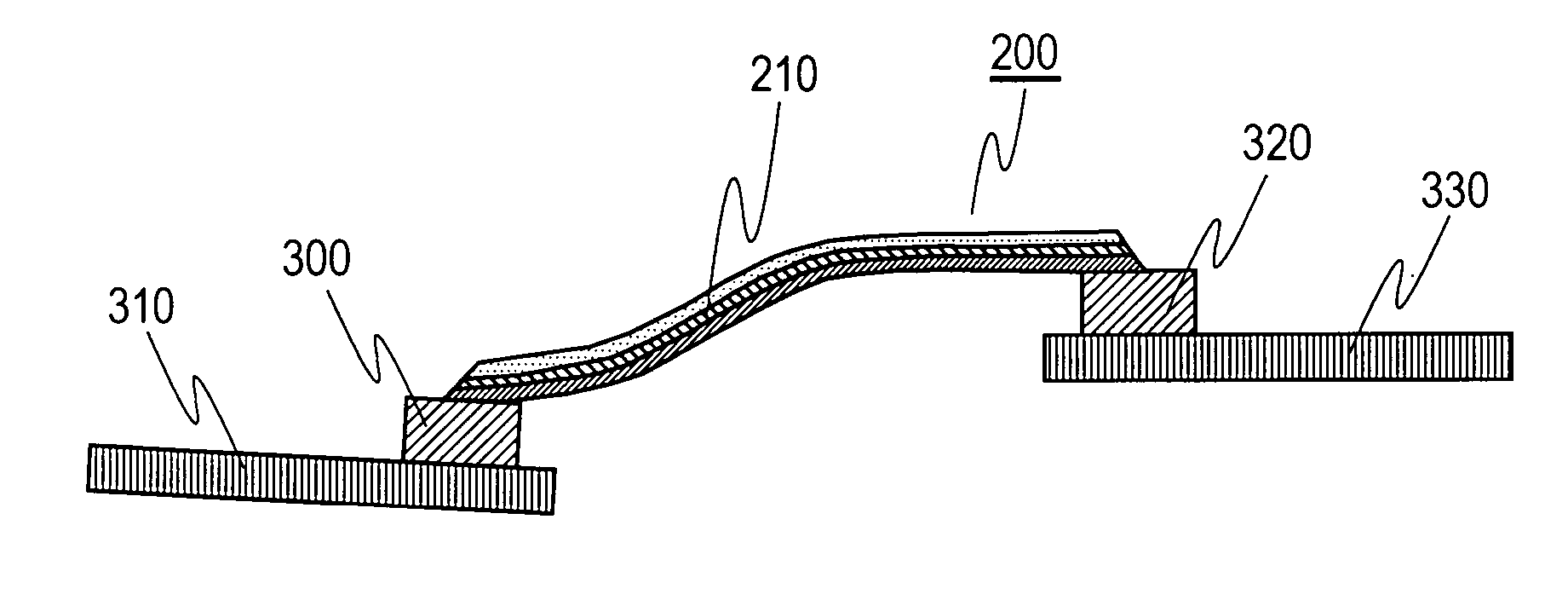
[0123]FIG. 13 is a transparent perspective view showing the shape of an optical waveguide film used in a portable device according to Embodiment 3. This configuration is the same as Embodiment 1 except that the shape of the optical waveguide film 200 near the opening and closing of the connection section 120 is formed as an already bent shape 460.
[0124] Embodiment 3 reduces further the optical loss caused by the bending stress in the optical waveguide film 200 used in a portable device according to Embodiment 1. The reason for this is described below. As described in Embodiment 1, the mechanism of the optical loss caused by bending is that material distortion caused by the bending stress generates a change in the relative index difference of the core and the clad. That is, in the folding operation of the portable device, in case that the stress in the optical waveguide film 200 is minimum in an opened state, the generated stress reaches the maximum in a folded-...
PUM
 Abstract
Description
Claims
Application Information
 - R&D
- Intellectual Property
- Life Sciences
- Materials
- Tech Scout
- Unparalleled Data Quality
- Higher Quality Content
- 60% Fewer Hallucinations
Browse by: Latest US Patents, China's latest patents, Technical Efficacy Thesaurus, Application Domain, Technology Topic, Popular Technical Reports.
© 2025 PatSnap. All rights reserved.Legal|Privacy policy|Modern Slavery Act Transparency Statement|Sitemap|About US| Contact US: help@patsnap.com


